
See Part 1 of Laser surface preparation of composite materials
DCB testing
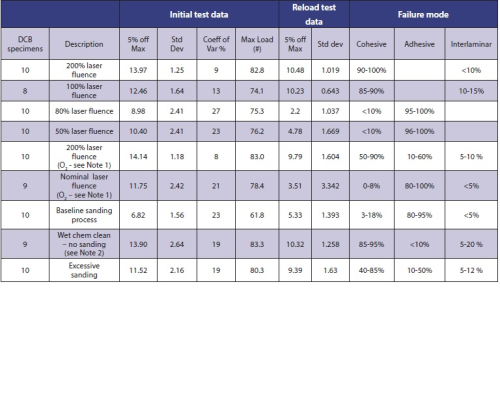
For this project, Delsen Testing Laboratories in Glendale, CA, fabricated and tested DCB (Double Cantilever Beam) specimens in accordance with ASTM D5528. Test data are shown in Table 1.
Following crack initiation, ‘re-loading’ of the test specimen produces load-displacement data that record the strain energy release rate as the crack propagates through the length of the adhesive bond joint. Several factors influence strain energy release rate, including adhesive strength, substrate flexural stiffness, and failure mode. The DCB data document the 5% off-maximum GIC values that were measured during the tests.
A second important characteristic measured in the DCB test is the failure mode, meaning whether the eventual failure was adhesive, cohesive, or delamination. A discussion on composite bonding failure modes is presented in the separate box. In general, composite surface preparation procedures seek to eliminate adhesive failure modes, which indicate low bond strength and low failure toughness. Ideally, DCB testing would produce only cohesive and interlaminar bond failures, with no adhesive bond failures. That is exactly the result that this testing produced.
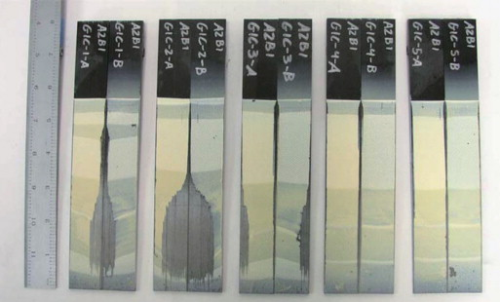
In addition to fabricating and testing DCB specimens, Delsen Laboratories also analysed the DCB load-displacement data and the failure mode area ratios of the test specimens. Figure 3 shows DCB failure surfaces. The DCB data in Table 1 show a monotonic correlation of higher GIC values with higher laser fluence. Furthermore, higher laser fluence levels reduced the variability of GIC values, as measured by the standard deviation and coefficient of variance (CV) in the DCB test sample populations that were processed with the two higher-fluence laser conditions.
|
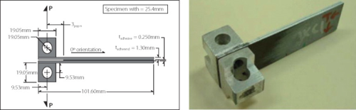
The failure toughness of bonded joints can be quantified by measurements of failure mechanics-based bond properties. Evaluation of different surface preparation methods in this project was based on DCB tests per ASTM specification D5528, Standard Test Method for Mode 1 Interlaminar Fracture Toughness of Unidirectional Fiber-Reinforced Polymer Matrix Composites. The DCB test defined in ASTM D5528 measures the critical value of the Mode-1 strain energy release rate (G1C) as an induced crack propagates through the plane of the adhesive joint between the faying surfaces of the bonded joint specimen. G1C values measure adhesive bond failure toughness. The DCB tests also included analysis of the failure modes exhibited by the specimen surfaces (for example, adhesive, cohesive or interlaminar). Failure mode analysis provides key information about failure mechanisms and bond quality. DCB testing is designed to quantify the Mode-1 failure toughness of an adhesive bond by measuring the critical value (5% off-maximum) of the strain energy release rate (GIC) during the propagation of an induced crack through the plane of the adhesive bond between the faying surfaces of the two bonded substrates. Load blocks attached to each side of the DCB specimen provide attachment points to a tensile dynamometer that generates the mechanical forces for the test. The standard D5528 test article is a 1 inch × 4 inch (25.4 mm × 101.6 mm) specimen with the zero-degree fibre orientation in the longitudinal axis of unidirectional composite substrates (see examples in Figure 3). During the DCB test, crack initiation and propagation is achieved by the application of tensile loads through the load blocks, normal to the short-transverse direction of the adhesive bond line. These loads are identified as force P in the drawing in Figure 4. As the two bonded substrates are pulled apart, crack propagation occurs, and the force required to maintain propagation is recorded. |
The 100% fluence condition corresponds to a laser scan pattern with the minimum overlap of laser-illuminated spots necessary to assure full coverage of the target surface with laser illumination. Samples prepared with the 100% laser fluence condition showed 85-90% cohesive failures, with the rest interlaminar. The 200% fluence condition incorporates twice the fluence level of the 100% condition. Delsen Laboratories’ analysis showed that samples prepared with the 200% laser fluence condition showed 90-100% cohesive failures, and the rest interlaminar.
At the 200% laser fluence condition DCB tests with air and oxygen purge produced results equivalent to values obtained in construction of the F-22 aircraft, widely regarded as the apex to date for composite bonding (Melcher et.al.). Significantly, there were no adhesive failures in samples processed with either the 100% or 200% laser conditions.
The 100% fluence level appears to be the threshold laser condition for effective surface preparation. Laser conditions at lower fluence levels − 80% and 50% - produced low G1C values with mostly adhesive-mode failures. At these lower process conditions, the laser does not treat the entire surface. Lower adhesive bond toughness values reflect this incomplete bond joint coverage.
DCB test results
DCB test data for the aircraft manufacturer's baseline surface preparation process showed high variability, as was expected from a manual procedure. In addition to the higher variability in the manual abrasive process outcomes, SEM and optical microscopy also showed that manual abrasive processes consistently damaged the near-surface carbon fibres of the test substrates. This damage is undesirable, and stands in contrast to the laser-processed samples, which showed no damage of any kind to the carbon fibres.
DCB test results across the populations of laser-processed and baseline manual abrasive- processed samples show:
- The measured G1C values from the high-fluence laser process had a coefficient of variance (CV) value less than half that of the baseline manual abrasive process. So, the laser-processed samples had much greater repeatability than their baseline counterparts.
- The measured G1C values for the high-fluence laser process were highest of any test population, including the baseline manual abrasive process. So, the laser-processed samples showed greater bond fracture toughness than their baseline counterparts.
These improvements are very significant for composite manufacturing applications.
Notes:
1.Two rounds of laser surface prep were performed in a pure oxygen environment to determine whether oxygen partial pressure at the substrate surface during laser ablation would influence the DCB results. 2.This process used for testing only, and is not for production use.
Conclusions
1.Laser surface preparation, using the appropriate laser recipe and closed-loop control, can bring significant improvement to the consistent repeatability of both:
- a) the process of bonding composites together, and
- b) the outcomes of that process, principally manifest in much more consistent bond performance. Measures include higher G1C values, complete elimination of adhesive failures, and greater than two times improvement in outcome repeatability.
2.Laser processes are inherently scalable and compatible with various modes of factory automation. This compatibility would enable greater throughput and tighter control than conventional methods of composite surface preparation.
Each of these results is significant in the context of manufacturing composite airframes and components. Taken together, they arguably represent a breakthrough.
Further information
General Lasertronics Corporation; rcargill@lasertronics.com
Lasertronics designs and manufactures specialised laser systems for coating removal and surface preparation. Lasertronics’ systems incorporate unique closed-loop, real-time electronic control technology that provides a precise, repeatable distribution of laser energy on the target surface, while protecting the substrate from any changes in material properties.
See Part 1 of Laser surface preparation of composite materials


