

Condition monitoring is now highly regarded, indeed insisted upon, as a technique for protecting the mechanical drive trains of in-service wind turbines. The need for it becomes more critical as turbine size steps up from the present 1.5-2.5 MW median range to 3-3.6 MW and even towards 5 MW and higher offshore. Until recently rotor blades, with their few moving parts, have not generally been accorded the same protection. However, given the increased size of modern turbine blades – 90-130 m long on the latest high-power or low-wind machines – and their growing fabrication sophistication and cost, blade monitoring is becoming important to operators and insurers alike. The consequences of any structural failure, especially offshore where replacing a damaged blade weighing a dozen or more tonnes is a major undertaking, are increasingly expensive. Condition monitoring offers the chance to avoid such failures and to keep a degraded rotor turning until the next scheduled maintenance period.
A study conducted by the Wind Energy Department at Denmark's Risoe National Laboratory concluded that remote surveillance of rotor blades of large offshore wind turbines has clear economic benefit. Several monitoring techniques are available, a number of them relying on fibres and sensors that can be embedded within reinforced plastic blade structures.
The Risoe team assessed three sensor types:
- accelerometers;
- acoustic emission detectors; and
- fibre-optical strain gauges.
They found that all worked satisfactorily and could complement each other. They characterised acoustic emission as being best able to detect and locate small laminate flaws, and fibre optic displacement transducers as being especially effective in detecting adhesion failures. Accelerometers sense vibration along with changes and trends that can indicate incipient damage.
A follow-up project (McGugan et al. 2006) developed specific strategies for blade instrumentation and data interpretation, these having subsequently been verified in full-scale tests by blade manufacturers. Risoe has since successfully retrofitted sensors to in-service rotors and product development agreements now exist with blade manufacturers.
At an international level, Risoe National Laboratory has been active within the European Union's five-year (2006-2011) UpWind project, concentrating on condition monitoring activities for offshore wind turbines, towers and blades. One of the work packages, devoted to the integration of new blade condition monitoring and fault prediction approaches into the next generation of turbines for offshore wind farms, is focused particularly on the use of optical fibres. An important aim within the programme is to promote standardisation of aspects such as power calculation, sampling rates, data storage and communication, digital/analogue conversion, signal conditioning hardware etc., so that technology suppliers can provide equipment that is both widely applicable and compatible with supervisory control and data acquisition (SCADA) schemes used for overall wind farm control.
Parallel work is taking place elsewhere. For instance, the National Renewable Energy and Sandia Laboratories in the USA have experimented with stress wave analysis, in which low-frequency stress waves are injected into the blade via bonded piezoceramic patches, which also receive the returns.
Tests have shown that changes in stress wave parameters, resulting from small initial changes occurring in the structure, can be a useful predictor of failure. The technique's cost remains an issue, however, and more affordable options are currently preferred for in-service use.
For example, a simple way to detect incipient cracking or buckling is to embed optical fibres in strategic areas within the composite laminate and check that light paths down the fibres do not become interrupted – that is, the fibres remain continuous.
Another option relies on the fact that it is easier to measure loads on blades than it is to detect faults directly. Loads experienced in service may, for example, be compared with those predicted at the design stage by finite element analysis (FEA) and any discrepancy can prompt a re-assessment of blade fatigue life. Blade loads are measured using strategically placed electrical or fibre optical strain gauges. Loads that occur at certain frequencies, such as those due to tower shadow and the cyclic reversal of gravitational load experienced at each blade revolution, are amenable to statistical analysis tools developed for use with rotating machinery, such as fast fourier transform (FFT) analysis. However, wind turbulence is a random broadband phenomenon and is less amenable to such tools. Even so, wind can excite resonances at specific frequencies and these can be damaging. (Sea waves can do the same, via the support towers.) Accelerometers can be used to sense and track these resonant vibrations, frequency-based analysis then being used to reveal changes resulting from material fatigue or other degradation.
Whatever type of sensor is used, interpreting the signal returns is complicated by the layered bi-phase nature of the plastic laminate. Intelligent signal processing incorporating a range of analysis techniques is needed to meet the challenge. Having a plan of the composite lay-up and ‘mapping’ the blade in software can also help address the difficulty.
Fibre optic merits
Electrical strain gauge sensing is affordable, well proven and widely used. However fibre optic sensing, though more recent and more expensive, has a number of advantages. Electrical systems can be subject to drift, a problem to which fibre optical strain gauges are less prone. The data capacity of optical fibres is far superior to that of wires. Optical fibres do not conduct electricity and, because they are consequently impervious to electromagnetic interference, they are highly resistant to lightning strikes, a significant issue with large rotors. Embedding fibre optic fibres and sensors within the laminate offers a more durable solution than wired systems, which are typically surface bonded and may suffer disbonding and metal fatigue over a blade's lifetime. (Surface-bonded systems are, however, more easily repaired.)
An optical fibre consists of a core and a cladding. The core has a higher refractive index than the cladding such that light is continually reflected back into the fibre and propagates along the core by total internal reflection. The fibre can therefore be thought of as a conductor of light rather than electricity. Various protective jackets are available and a selection can be made that is compatible with the laminate scheduled to be monitored.
At around 125 mm diameter, a conventional telecommunications grade optical fibre is considerably smaller than typical reinforced plastic glass fibres and can be surface mounted or embedded within the laminate. When coated with a protective layer of acrylic, polyimide or other polymer, optical fibres have good adhesion with standard reinforced plastic fibres and resins and are suitable for embedding.
Care has to be taken when installing glass optical fibres as they are brittle and can easily break. When aligned axially with the unidirectional fibres within the blade, embedded fibre optic fibres do not materially affect the tensile mechanical properties of the laminate though, if they are installed off-axis, there may be some effect on compressive properties.
Fibre optical sensors are small, light and (like the optical fibres themselves) are readily embedded in composite structures or bonded to components. This opens up the possibility of distributed sensing with measurements being taken at numerous points throughout the blade laminate structure. According to industry sources, fibre optic devices are readily incorporated into the laminate as part of any of the normal production processes – hand lay-up, vacuum infusion, prepreg etc. Service experience to date suggests that fibres and sensors have good long-term static and dynamic fatigue performance, and are able to withstand high levels of shock and vibration. Stability and reliability over time appear not to be an issue. Optical fibre devices can be used to measure other parameters, such as temperature and vibration, as well as load/strain. They can be produced in volume inexpensively.Optical strain sensors operate by detecting the slight bending that results from blade loading and hence strain. As a fibre bends with the blade under wind loading, the way different wavelengths within the light passing through the optic are reflected and refracted is altered and this results in a change in the wavelength (colour) spectrum emerging from the end of the fibre. The amount of this alteration is a measure of the amount of bend in the fibre. Two types of sensor can be used to detect and quantify this change, fibre-Bragg gratings (FBGs) and extrinsic Fabry-Perot interferometric (EFPI) sensors.
In the interferometric method, light altered as a result of fibre bending is brought together with a sample of the unaltered light first propagated along the fibre, to create an interference pattern. Examining changes that take place within the interference pattern as the fibre optic system responds to loads on the blade can reveal even the slightest amount of bend, making the system highly sensitive.
A fibre Bragg grating (so called after the scientist who first pioneered use of the effect) offers a convenient means of quantifying the strain-induced spectral change electronically. FBGs emit light at a particular wavelength (colour) when broadband (white) light is directed at them. The precise wavelength (colour) of the emission varies according to the amount of bend/strain to which the fibre containing the FBGs is subjected. The monochromatic Bragg emission is readily converted to an electrical analogue which is suitable for subsequent digital electronic processing.
Because the FBG wavelength increases linearly with the applied load, it offers a useful measurement of strain. FBG sensors are affected by temperature as well as strain, so temperature-compensating electronics have to be part of the processing chain. (Alternatively, by filtering out the strain term instead, temperature can be measured.)
FBGs are easily incorporated into optical fibres as part of the fibre manufacturing process. Over 100 sensing elements can be written into a single 250-mm diameter optical fibre – a simple way of providing multiple sensor installation and connectivity. Each grating consists of a series of closely spaced bands of glass having different refractive indices, such that the boundaries between the bands can reflect incident light. When light from a source located at one end of the optical fibre encounters the FBG, some of the incident light is reflected back from the boundaries. If the inter-band separation distances and the light wavelength ‘tally’, the reflections from successive bands are additive and the FBG transmits the single resulting wavelength, suppressing others.
Commercial systems
Embedded FBG technology is at the heart of LM Blade Monitoring, the intelligent monitor marketed by Danish blade specialist LM Glasfiber as an option for its larger blades.
Prototype systems were first fitted to LM 40.0P and 61.5P models. Accurate load monitoring also helps, says LM, in pitching rotor blades individually (rather than collectively) in such a way as to minimise imbalance and off-axis loads. These unwanted loads elevate stresses on the drive train, tower and even the tower foundations, shortening turbine service life overall. They may arise for mechanical reasons or because (as a result of large rotor diameters) blades near the top and bottom of the circle of rotation see different wind speeds.
According to LM, accurate individual blade pitching can bring about a 15-30% reduction in flapwise fatigue loads and 10-30% reduction in tower yaw and tilt fatigue loads.
FBG-sensed load data is combined with optical fibre crack detection, vibration and temperature sensing, lightning detection and rotor position/pitch angle measurements in a comprehensive condition monitoring solution. Inputs are processed in a blade computer to provide early warning of any damage. Potentially, optical protection can be extended to towers and foundations.
Southampton, UK-based company Insensys Ltd markets its own innovative fibre optic/FBG-based solution intended both for structural health monitoring and for independent blade pitch control. The company's business development manager, wind energy, Phil Rhead is a powerful advocate for the advantages of fibre optic monitoring technology.
“Rotors are a challenging environment for any monitoring technology and, in particular, lightning strikes are not infrequent,” he declares. “All the signal paths within a fibre optical system are resistant to electromagnetic interference and are substantially lightning proof. Compare that with conventional systems where, for example, lightning frequently tracks back to the in-hub amplifiers, which then have to be replaced. As well as damaging the electronics, lightning strikes often destroy and de-bond conventional electrical sensors. The chances of a strike increase with turbine size and height, and with offshore location.”
Rotors are a challenging environment for any monitoring technology. In particular, lightning strikes are not infrequent.
While electrical (resistive) strain gauging is still the dominant technology for test and measurement companies, the conviction has grown over the last five years that optical technology is an inherently superior alternative for the real-time monitoring of rotors in service.
“I believe this is the only reliable way to do it [measure strain],” Phil Rhead told Reinforced Plastics. “We’ve had our system trialled by leading turbine manufacturers, test houses and research labs and have not yet had a sensor fail during operation.”
While conceding that fibre optic sensors are more expensive than conventional electrical strain gauges, Rhead argues that, by the time installation time and cost are taken into account, costings for commissioned systems are similar for both solutions. Experience with certain prototype wind turbines fitted with dozens of fibre optic sensors for test and qualification purposes suggest that the economics are acceptable and that large amounts of data can be harvested successfully by this method.
An Insensys system for application to a wind turbine rotor comprises three channels, one per blade. Four strain sensors (typically) located mutually at right angles at the root of each blade provide two pairs of strain measurements, one pair each for edgewise and flapwise bending moments. This number is currently considered optimum for most in-service systems, though as many as 60 sensors might be fitted to a prototype system for test purposes.
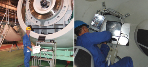
Sensors are either embedded during blade manufacture or retrofitted, and are connected to looped optical fibres that are similarly embedded or bonded to the blade. For each blade, a connector box embedded or retrofitted at the blade root provides all necessary connections between the blade and the hub, as well as light sources for projecting light along the optical fibres. An interrogator unit in the blade hub interrogates the fibre sensors and receives the responses.
The Insensys technology interfaces readily with other manufacturers’ monitoring and control systems, for instance the ProCon system from SKF Condition Monitoring, a company that specialises in monitoring gears and rolling bearings.
SKF contends that monitoring both blade health and turbine drive train health with the same integrated system improves the quality of condition monitoring overall by relating drive train degradation to the rotor-induced forcing loads that cause it. A bonus from relating cause and effect in this way, the company points out, is that results recorded over time can help manufacturers to improve the design of turbine components and help operators to devise effective load reduction strategies.
Monitoring a dozen or more sensors in a rotor 30 times each second, the Insensys instrumentation rapidly generates copious data. The system performs statistical analyses on blade bending data in both time and frequency domains to extract key information and passes a summary to the condition monitoring system. Alternatively, it is passed to a data logger for subsequent retrieval and analysis. From the data, the system can calculate individual blade loads and can make inferences about blade condition, especially if more sensors are installed in the blade than the two pairs at each blade root mentioned above. Storing and analysing load service histories enables blade residual fatigue lives to be predicted. Though this is not yet an exact science for composites, because of the still limited knowledge of the long-term degradation behaviour of these highly variable materials, the experience base is constantly growing, permitting on-going refinement of the predictive algorithm.
A second role for the Insenys system is to facilitate individual blade pitch control. The electronic box that processes the fibre optic sensor inputs feeds outputs to the wind turbine's programmable logic controller (PLC) or blade pitch controller. As a result, the PLC or computer commands blade pitch movements, both individually and collectively, according to the wind conditions prevailing at each blade.
Independent pitch control is increasingly regarded as a ‘must have’ for the next generation of larger turbines. It can enhance structural efficiency, and enable the rotor to accommodate a wider range of adverse flow conditions. Potentially, it can permit a larger, higher-yield rotor for a given nacelle and support structure.
With its potential to minimise operation and maintenance expenses, to mitigate risk for insurers and to enhance turbine yield, rotor blade condition monitoring is attracting growing interest from cost-conscious wind farm operators. Conditioning monitoring can make a major contribution to enabling these crucial wind turbine components last their full design life of 20 years (nominally), equating to about 120 000 operating hours (whereas car engines typically average only some 5000 hours per lifetime).
Depending on the method chosen, continuous autonomous condition monitoring should pay for itself several times over by reducing maintenance costs, preventing serious damage, extending maintenance intervals, and widening the envelope of weather conditions within which turbines are cleared to operate. It will also provide trend data useful to those responsible for designing new and improved generations of the large composite rotor blades that are helping to drive wind power into the energy mainstream.


