
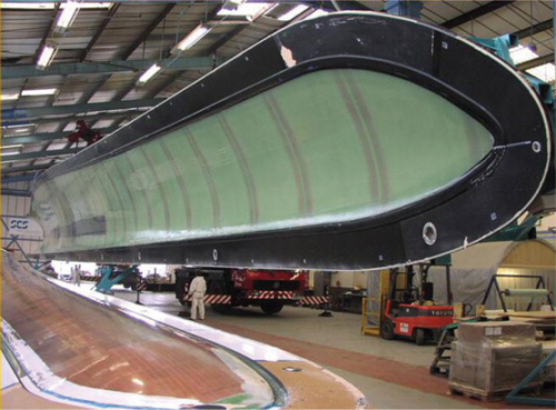
“Some of these blades are very big indeed, among the largest reinforced plastic items produced today,” asserts Matthew Chalk, operations director of Solent Composite Systems of Cowes, Isle of Wight. “We produce moulds between 30 and 45 m long and have recently had enquiries about tooling for 55 m blades.”
A complete tool pair for a 40 m blade can weigh some 16-18 tonnes. Around a quarter of this weight is made up of composites, the remainder being accounted for by the rigid steel backing frame. Mould tools rarely turn out the 300-400 blades sets for which they are generally rated, before they are made obsolete by new blade models. They then have to be replaced by fresh tooling. These facts all indicate that blade tooling itself constitutes a substantial composites market sector.
Composites have risen to the challenge that moulding huge aerofoils provides. Metal moulds, still used by some manufacturers of smaller blades, are generally regarded as too heavy and unwieldy in the sizes required for prevailing multi-megawatt (MW) machines. Composites are much lighter. They have less thermal inertia and their coefficients of thermal expansion (CTE) naturally match those of blade materials, unlike metal where mismatches can create difficulties during in-mould thermal cycling. Reinforced plastic moulds can be made to any desired shape with less material wastage and, though they are perceived to be less durable than metal equivalents would be, rapid blade evolution and obsolescence make this a non-pressing consideration. Material technology has developed in line with blade producers' growing preference for resin infusion manufacture. Now that it is possible with composite tooling to achieve a smooth, fair mould surface with high vacuum integrity, infusion is rapidly becoming the process of choice for significant series production.
Solent Composite Systems (SCS), which started out as a division within SP Systems (now Gurit) and went separate in 1996 as Offshore Composite Structures before becoming SCS in March 2004, made its first blade moulds, a matched mould pair for a 23 m blade, in 2000. It had been approached by NEG Micon, later acquired by Vestas, because it had a background in items produced in composites and steel for the offshore oil and gas sector. It supplied two moulds for the 23 m blade and several moulds for a subsequent 31 m model. The fact that these were supplied complete with steel support frames, microprocessor controlled heating elements, three-phase electrical services, resin distribution system and vacuum services, set a pattern for the future. Since then, the company has grown in capability along with the evolving needs of wind turbine producers. Its expertise is embodied in the semi-standard SmartMould™ and rotor blade manufacturing system (RBMS™) technologies, which are aimed at providing complete integrated blade manufacturing systems with full associated services. To assure wind energy clients that it can meet highest quality, environmental and safety standards in its operations. SCS has secured ISO 9001, 14001 and OHSAS 18001 approvals and claims to be one of the first UK companies to achieve all three as an integrated management system.
Blade design
The mould producing process begins, says Matthew Chalk, with a close examination of the design of the blade for which tooling is required. Chalk emphasises the importance of forming a good working relationship with clients right from the start so that all the relevant facts and requirements are known and understood. The customer's design philosophy, the materials intended to be used, the blade dimensions, its aerofoil shape, design life and other factors are all taken into consideration. In particular, the dimensions must be known precisely since these will be incorporated into a CAD model, and subsequently applied via CAM to achieve an accurate tool profile.
“A good understanding of the client's philosophy enables us to make suggestions that might influence the blade's final design,” says Chalk. “We're really helping the customer design for production. An atmosphere of open communication helps secure the best results.”
A typical blade is made by moulding two half shells in a pair of moulds. A spar cap (analogous to the spar in an aircraft wing), web stiffeners (ribs) and other details are installed into one of the halves and adhesive is applied to all the exposed bonding edges. The second half shell is then turned over, still in its mould tool, and lowered onto the first, whereupon the adhesive is allowed to cure, joining the two halves of the blade together. Such blades therefore require a tooling set of two main moulds plus separate moulds for the web stiffeners and spar caps – at least half a dozen tools in all. Further moulds may be associated with blade edges and root ends.
“Because we engineer and supply all of these,” declares Chalk, “together with all associated services installed, we refer to our product as a complete blade mould manufacturing system. Albeit, the biggest and most challenging tools within the set are the main shell half moulds.”
Each of the latter comprises a composite tool on a mild steel backing frame.
“The steel-backed composite mould has become our preferred basis,” says Chalk, “especially now that blades have become large and complex with twist, pre-bending and specific edge shaping.”
For a long, relatively narrow mould to maintain the required blade shape, the backing structure needs to be strong and rigid. Typically a finished 40 m long truss structure should not bow (sag) more than 5-10 mm over its length when supported at its ends. Extra strength is required at lift and hinge points where the highest loads can be expected. SCS designs its structures to be close to the ground so as to minimise height and the consequent need for access platforms during blade fabrication operations. Welding of the steel frame is carried out by qualified welders and all joints are non-destructive testing (NDT) inspected using magnetic particle inspection.
For a complete mould pair, two sets of the ‘ironwork’ are hinged together at one side so that the mould can be opened clamshell fashion. The hinges used are of a proprietary (SmartHinge™), hydraulically powered or crane lift-hinge design which ensures that, once the mould is closed, the last part of the upper tool's travel is vertically downwards. This ensures that the glue lines that will bond the two half-blades remain undisturbed until the halves have come fully together.
SCS uses wet infusion to produce the main mould tools. This is a clean manufacturing process offering minimal operator exposure to resin, full emissions capture and the ability to position fabric in the absences of resin. At one time, SCS investigated the possible use of prepreg material for tools but ruled this out because of issues involved in shaping these stiffer forms to all the moulds required for a complete tooling system.
Each half mould is made from resin-infused glass and/or carbon fabrics. Glass and carbon content is located in positions in the tool that will coincide with where these materials are used in the blades to be moulded. Fabrics used are woven rather than stitched. The resin is often epoxy, though vinyl esters and polyesters can be used. Grades employed are optimised for infusion and high-temperature tooling applications
Some blade producers require a gel-coat as the inner mould surface, others do not. Gel-coats are sometimes seen as a way of achieving the best possible blade surface, free of the voids that can be present in mouldings produced by wet lay-up or from prepregs.
“On balance,” says Chalk, “we prefer to do without a gel-coat. We see it as another interface that could possibly fail. We have developed techniques for producing a good surface with high vacuum integrity which, with no gel, you can see so that you can make good any imperfections very locally.”
Polystyrene plug
The process of producing a main shell mould starts with a polystyrene foam blank used to manufacture a plug. Plugs are made in 6-8 m long modules, which can be joined and separated as required. This provides the flexibility to change individual modules as changes are made to the blade design
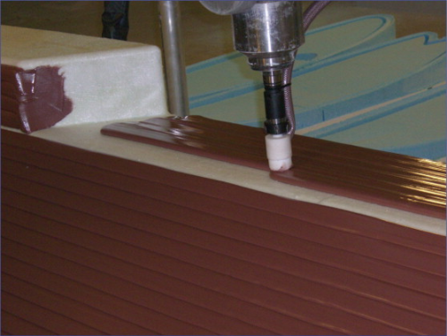
First, the blank is machined to its approximate final shape. A tooling paste is then applied or, alternatively, the machined polystyrene can be over-laminated. The second method may be more affordable, but makes it harder to secure an accurate tolerance of the surface profile. The next step is to machine the outer surface, under CNC control, to fine tolerances. If necessary, the milled surface is sanded and polished to a flawless finish. The plug is then ready for application of the release system and subsequent lamination of the mould.
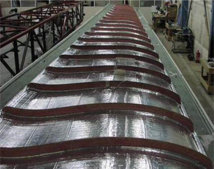
Laminators first lay fabric layers onto the plug, the lightest fabrics first and the heaviest on the outside. Most are laid across the plug, though some will be placed longitudinally. Heating elements are included on the back surface, with a subsequent layer of metal foil to spread the heat. Matthew Chalk explains that an electrical heating system is generally preferred for its zoned control possibilities.
“Blade laminate characteristics vary considerably from the root end, which is very thick and can be expected to exotherm substantially during the in-mould cure cycle, to the much thinner tip where exotherm will be negligible. Accordingly, heating requirements vary along its length. For that reason we need zonal heating and an electrical system facilitates this. A PC provides a convenient control interface and also logs all the data for process traceability purposes. Our control system is 100% redundant, contributing to process integrity.” (Heating elements, however, are not duplicated as they are highly reliable).
In a few cases, generally where an unusually high production rate requires active cooling as well as heating, a hot/cold air system is used, but normally the solution is electrical. In operation, each zone of the mould tool is independently controlled and thermocouple monitored so that the required temperatures, ramp rates and cure times can be achieved.
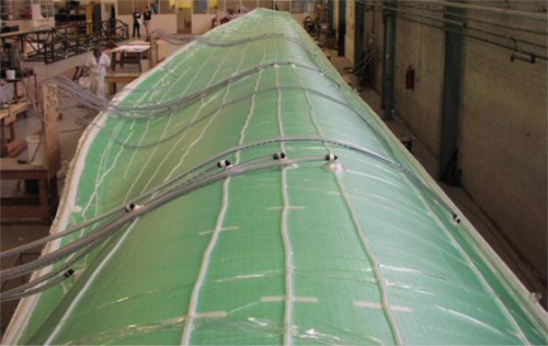
At a late stage in the preparation of the mould laminate, resin feed lines and galleries are laid into the mould system. Locators, to ensure that the mould halves will line up precisely when they come together, are moulded in. Other items, vacuum lines and compressed air pipes for hand tools for example, are added to the framework.
“We aim to supply clients with complete ‘plug and play’ tooling systems that are ready for use, self-contained and mobile,” explains Chalk. “Customers like them to be easily movable in and out of factory areas, without having to deal with masses of leads and pipes.”
Next, the entire laminate is vacuum bagged and taped. Resin is infused into the dry laminate under vacuum. The infused tool undergoes an initial cure, at a temperature a little above ambient, for up to 24 hours. The laminate is then subjected to a post-cure, typically overnight at 50–60°C. This relatively benign cure regime is favoured because it avoids internal stresses building up in the laminate structure. Test pieces comprising mould cross sections together with heating elements may be used to verify that cure conditions and responses previously calculated using finite element analysis are actually achieved.
As the next stage, stiffeners are laminated onto the back of the mould. These serve to spread loads during blade demoulding operations. Finally, the fabricated steel truss backing structure is added, after which the mould is ready for use.
A complete mould set also requires tooling for the spar caps and webs. Those for the spar caps, which can be complex in shape, are likewise laminated on plugs, working from 3D CAM. Web moulds are generally simple and flat.
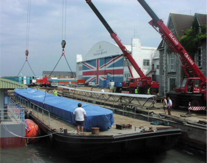
Multiple sites at Cowes, with headquarters at Cowes Waterfront Venture Quays, provide SCS with design, engineering, prototyping and manufacturing workspace, with current capability to produce large-scale moulds up to 50 m long. Work processes are tightly controlled and accompanied as appropriate by risk analyses and individual quality plans. Deep water access to manufacturing sites enables completed moulds to be loaded onto barges for delivery to Southampton Docks and onward shipment to anywhere in the world.
In the competitive world of wind blade manufacture, client confidentiality requirements prevent SCS from saying much about current clients, but it has worked in the past for such names as NEG Micon, Vestas, LM Glasfiber, GE Wind and FKI DeWind. SCS also helps new entrants to the market establish their manufacturing systems. Mould tool manufacture is backed by comprehensive service packages as required. For example, the company can provide training, mould inspection and maintenance (SmartCare™), and assistance in engineering for production. One popular service is training operators to achieve best performance and life from their tooling systems. Structural and transport analysis of mould frames is available as part of their service, and the company can assist clients wishing to construct their own plugs and moulds. On occasion, other manufacturers' moulds have been resurfaced and refinished to make good surface damage.
SCS is a member of the British Wind Energy Association, European Wind Energy Association and the British Plastics Federation Composites Group.
Critical Interface
Arguably the most critical component in a wind blade tooling system is the tool surface, which interfaces with the blade surface and influences its ultimate aerodynamic qualities. Essentially this important interface surface has to be correctly profiled, smooth, seamless and vacuum-tight (for infusion processes). A popular method for achieving the required high-quality mould surface is to use tooling paste, either as the face of the plug or directly as the face of the mould tool. The paste, after it has cured to a solid, is CNC-milled to the intended profile and then finished as necessary. As Peter Soff, of Sika Tooling and Composites, Germany, explained to Reinforced Plastics, tooling pastes require very specific characteristics.
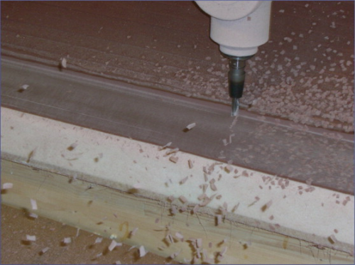
The paste should cure to a fine, dense surface that is smooth and can be machined to the required profile with minimal need for additional finishing. Ideally, machining in two steps, rough cut and fine cut, should be all that is required, says Soff. The final surface also needs to be seamless, something that is difficult to achieve with plugs or moulds made from wood or foam blocks/boards where, irrespective of all precautions, bond lines tend to show through. Further, the paste must be free of air bubbles, a factor which impacts both the basic formulation and the dispensing means.
Another requirement is high thermal tolerance; the surface layer must be sufficiently heat resistant to withstand thermal cure processes without distortion or cracking. According to Matthew Chalk of Solent Composite Systems, temperatures inside moulds due to applied heat and exotherm can in some cases rise to 100°C plus during cure cycles. Occasionally, this leads to a requirement for pastes able to withstand around 130°C in order to provide sufficient operating margin. Chalk foresees a need for pastes of higher thermal capability still, suitable for higher-rate manufacture of smaller blades expected to be used in future water turbines.
Also important and still a challenge to paste products is resistance to chemical attack. As well as delivering high mechanical properties, thermal tolerance and chemical resistance, a finished paste surface needs to be durable so that, if it is used directly in a mould, items can be moulded from it in significant numbers without degradation. The cured surface must be readily machinable, preferably with minimal generation of dust and residue that could block or blunt the milling tool.
Epoxies, suitably optimised for the tooling application, have tended to be the resin of choice for wind blade tooling, but Sika has an alternative approach for which it claims significant advantages. As Peter Soff points out, most epoxy-based pastes are produced by mixing two components together so that a cure can take place. These A and B components are already in paste form and, once they are mixed, there is no possibility of controlling how thick and ‘spreadable’ (thixotropic) the final dispensed paste is. However, using Sika's liquid-based polyurethane (PUR) paste system results in a more adaptable and faster extrusion process for large tools.
“With the PUR system, the level of thixotropy of the two mixed components is influenced by the dwell time - the time the mixed materials spend progressing from the mixing head to the dispensing nozzle,” according to Soff. “Users can therefore adjust the thixotropy level by controlling the dispensing rate. Their aim will be to dispense material that is creamy and not too stiff. Then it will be possible to place dispensed beads next to one another so that they merge without air entrapment. Automatic dispensers so adjusted will deliver a paste that cures to form a surface having the required mechanical and thermal properties.”
Soff reports that because the liquid A and B components are pumped rather than pressed, they are free of the entrapped air that is sometimes present in paste where both initial components are thixotropic. The final laid paste is therefore free of associated soft spots that can mar the subsequent milling process.
The liquid PUR approach also, Soff argues, saves time by speeding up the dispensing process, typically to 5 l/min or more. Liquid systems lends themselves to continuous dispensing without stops and restarts. No post-curing is required to reach the required Tg level and the material hardens much faster than epoxy paste. All this yields savings in time and energy usage. Another plus, holds Soff, is that PUR systems are generally about 25% more affordable than epoxy paste systems. Moreover, they can be put down less thick. Using automatic dispensing, thickness can typically be cut from 22 mm to 15 mm and below, further reducing cost.
Sika Biresin® M72 is a paste, suitable for wind blade tooling plugs, that offers a combination of the required properties, including good adhesion to expanded polystyrene. A later and more versatile formulation of the liquid PUR system, dubbed ‘New M72’, is said to provide an even finer, denser surface quality. According to Peter Soff, New M72 Biresin contains lower amounts of fillers than comparable epoxy formulations, and this has advantages when it comes to milling the hardened paste. Milling produces almost no dust, and delivers a surface finish from a two-step operation described as ‘equal to that of epoxy formulations.’
Other materials produced by Sika for tooling applications include a range of epoxy gel-coats and composite resin systems optimised for infusion and hand lay-up processes.


