
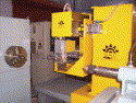
The filament winding industry looks like a growth industry again. After suffering through several years with stagnant growth, many of the companies producing machinery and software for the industry are reporting robust sales this year.
“The increase in sales over the past two years has been great,” according to John Green of the Green Sales Guy Co, the US agent for EHA Spezialmaschinenbau - BSD Filament Winding Technology. “Sales are definitely perking up.”
Much of this increase in sales is going into the developing world – primarily India, Asia and the Middle East.
“Sales for winders into the Middle East probably have increased by 30% per year over the past few years,” Green confirms.
“Our experience is that there has been significant growth in filament winding in India during the last 12 months and this looks set to considerably increase again in 2006,” notes Andrew Priestley of the Cadfil Filament Winding Software Company (Crescent Consultants). “This is not just in the low technology two-axis sector either, there is a major trend towards four-axis machines using the latest computer controllers.”
Mr B. Vijay Krishna of CNC Technics Pvt Ltd also says sales are brisk: “We have been selling machines to customers mostly in India, Australia, Malaysia, Vietnam, Thailand, Saudi Arabia, Qatar, and the UK.”
Krishna reports that CNC Technics has recently developed and delivered a six-axis filament winding machine with a Siemans 840D controller for the Indian Institute of Technology (IIT), the top Science and Engineering University in India, for its new composite centre. This system is also using the latest Cadfil filament winding software for axisymmetric shapes and non-axi-symmetric shapes such as pipe bends.
CNC Technics has also developed its own new control system named JOKAM, which is capable of controlling up to six axes simultaneously.
“This is a low cost controller with very little hardware and is extremely versatile,” claims Krishna. “It can run all popular winding program generation software.”
In Western Europe and the USA, a growing trend is the move to more automated, more integrated and higher throughput systems. John Green recently visited the Ragasco (a member of the Hexagon Group) facility in Norway.
“I was able to see the automated production of filament wound LPG tanks,” he reports. “I have never seen anything like this at any filament winding facility on earth. It was awesome. They are producing over 400 000 LPG tanks per year on a five spindle BSD winder. Two operators watch the automated production with very little intervention needed. Fully automated systems control loading and unloading of the mandrels, the resin bath level, automatic fibre tie-on, automatic fibre cut-off, and automatic loading of the wound parts into the oven. It was truly an amazing facility.”
Green reports that another facility, at Beko Technologies in the USA, has a BSD filament winding machine running 24 hours a day, 7 days a week making membrane filters.
“What is interesting is that the winder winds parts for many hours at a time with no operator around,” he notes. “This includes the night shift where the winder is continually producing filament wound filters. There are fibre breakage sensors to notify someone if a fibre breaks. Otherwise, the winder just keeps going and going.”
Joe Jansen of Magnum Venus Products reports that they see an increase in machinery going into the power industry and to companies that manufacture piping systems, with many customers wanting complete ‘turn key’ systems.
“Customers also want equipment for very large vertical/horizontal tanks,” he says. “We have supplied up to 120 ft (36 m) diameter machines.”
Jansen also sees an increase in machinery sales to the Middle East.
“We are selling about 50% domestic (US), with most of our international sales in Europe and the Middle East,” he states.
Many of the machines going into the Middle East are used to manufacture fibre reinforced plastic (FRP) pipe and tanks.
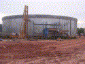
The increased demand for large diameter tanks is confirmed by Alfred Newberry of FEMech Engineering. He has just finished the installation of a very large vertical winding machine in Indonesia for the production of acid storage tanks. The tanks are 20 m in diameter and almost 16 m tall.
Green notes that BSD is also seeing more demand for ‘turnkey’ systems.
“More and more filament winding companies want to have a fully automated process,” he explains. “That is what I am seeing. BSD has done a few automated systems. They include CNG factories in China where BSD supplies the liner machine, the winding equipment and the ovens. BSD has also helped with fully automated pipe production systems in Europe. This is similar to the Ragasco set-up, but for pipes and tubes. There is fully automated handling of mandrels, automated winding, loading to the oven, unloading from the oven to the extractor etc.”
A growing trend is the move to more automated, more integrated and higher throughput systems.
Magnum Venus Products has also seen an increase in the demand for more automated, higher production, machinery. An innovation to address this need, that they have developed, is the ‘dual mandrel drive.’ It consists of a winding machine with two spindle (mandrel) drives, one on each side of the horizontal carriage. The delivery system can be swung 180° to allow winding on one side of the carriage while the part on the opposite side is being cured, removed or prepared for winding. This benefits their customers with time and equipment savings. The winding machine can always be winding with no waiting for mandrels to be moved in and out of the machine.
Advances
BSD has developed a new high precision resin bath.
“More companies are focusing on their total production process and fine tuning their resin baths to get better wet-out,” says Green. “This new resin bath is set-up for multiple spindle winders. The individual take-up arms are used for each spindle's take-up needs. They take up slack fibre, particularly in the turn-around areas. They can also be used as fibre breakage sensors.”
“Often, with a high quality resin bath, the customer can fine tune his process to use less resin, which is very important as resin prices increase, and have a better resin to fibre content on the part,” he adds.
A new patented pin-ring system developed by Ingenieurbüro für Kunststofftechnik (IBK) in Germany promises to improve filament winding at low winding angles. The pin-rings allow a much faster turn around of the fibre band at the ends of the mandrel, minimising material waste and winding time. The pins come in strips and can be cut to the length necessary for the mandrel diameter. The pins are secured to the mandrel before winding and then they are typically discarded after the part is cured.
Magnum Venus Products has developed a system to monitor the resin and fibre usage during filament winding. The system reports the run time amounts of resin and fibre being used. The operator can then make adjustments in the resin bath in real time to obtain the proper ratio of resin to fibre. In addition the final amounts of materials used at the end of the wind can be documented.
A new software plug in for finite element analysis (FEA) from Abaqus Inc, called ABAQUS Wound Composite, allows the company's ABAQUS/CAE program to analyse filament wound pressure vessels. The company is targeting existing ABAQUS users with the new plug-in.
Innovations
Companies using filament winding are known for the many new and innovative techniques and products they have developed over the years. That commitment to innovation continues today in many companies. One of the major companies in the Netherlands, Airborne Composites BV, is one of these highly innovative companies. It specialises in developing and producing advanced com-posite products and systems, with one of its latest innovations being new patented composite tubing for use in oil and gas exploration and production. The product is called Power & Data Transmission – Composite Coiled Tubing (PDT-COIL).
The technology allows manufacturing of continuous length thermoplastic composite tubing with integrated power conductors and optical fibres. The tubing can be coiled after manufacturing, producing very long contin-uous lengths with few splices. Preimpregnated thermoplastic composite tapes are wound on a thermoplastic liner and in-situ melt-fused and consolidated to provide a solid laminate. No autoclave or oven curing is required.
A thermoplastic matrix was selected instead of a classic thermoset composite because it provides:
- superior chemical resistance;
- higher allowable strain;
- ‘one material concept’: liner, structural layers, and coating are all of the same thermoplastic material, which eliminates any interface issues;
- higher impact resistance and improved robustness; and
- higher allowable operational temperature.
The complete range of thermoplastic resin materials can be processed, from polyethylene to PPS/PEKK/PEEK. Carbon and/or glass fibres are used to provide the required strength and stiffness. For the power conductors, a new design was developed to withstand the severe deformations during spooling of the tubing. The integral optical fibres are used for data transmission, strain monitoring and damage monitoring through acoustic emission.
A successful demonstration project using the PDT-COIL technology was recently completed. This project was carried out by an international consortium of Airborne Composites, Smartec, ETH Zurich, KU Leuven and Shell Global Solutions and was supported by the European Union. During this demonstration, a fully functional PDT-COIL demonstrator was connected to steel coiled tubing and to an electric submersible pump. Through the integrated power conductors, the pump was operated successfully.
|
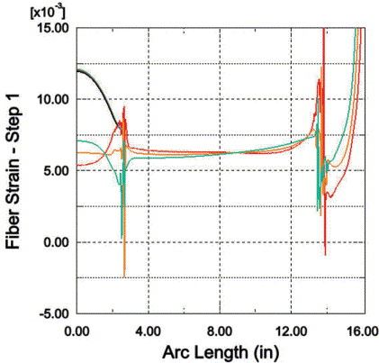
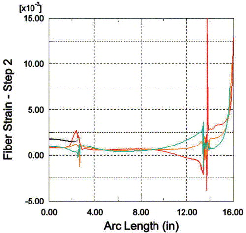
Filament winding can produce extremely high stiffness-to-weight and strength-to-weight structures compared to traditional all metal designed structures such as pressure vessels. Applications that capitalise on this are rocket propellant tanks and solid rocket motor casings for the aerospace industry and high pressure fuel storage tanks for hydrogen powered automobiles for the automotive industry. There is a difficulty in accurately predicting the behaviour of these structures that derives from the varying orientation of the wound filaments throughout the structure. The standard capabilities of commercial finite element codes are inadequate to model the variation of fibre orientation in a practical way. Thus, a plug-in for ABAQUS was developed – ABAQUS Wound Composite – to analyse a wide variety of axisymmetric wound composite structures. Features and benefits of the plug-in:
The construction of a filament wound pressure vessel begins with the selection of the underlying liner. The liner attaches to a polar boss that is usually constructed of a metal material and is used to mount end plates, rocket nozzles, or other components to the pressure vessel. Multiple bands of filaments are then wound over the liner in a helical pattern creating a wound layer. Alternating circumferential layers are added to increase the hoop strength. One layer after another is applied until the pressure vessel is constructed to the desired geometry. After the layers have been wound over the liner and have been cured, the liner is sometimes removed, leaving only the filament wound composite structure and in other cases, the liner remains as part of the pressure vessel. In some cases a rubber shear-ply is placed over the liner near the polar boss region in order to accommodate the relatively high shear strains that occur between the wound composite layers and the polar boss. The wound composite plug-in allows the user to define all of the necessary information to create, run, and post process a finite element model of an axisymmetric wound composite structure. Mesh and section creationCreation of the mesh is performed automatically by the wound composite plug-in. The user may choose the number of mesh seeds through the thickness of the layers and whether to constrain the number of seeds to increase, decrease, or remain constant. A target element aspect ratio may also be entered. The option of choosing a pure quad mesh, quad-dominated mesh, or a triangular mesh is provided. LoadingThe analysis is carried out in two steps. First, an ultimate pressure load equal to 1.5 times the nominal pressure rating is applied to the liner surface. The aluminum liner is yielded at this pressure and then the pressure is returned back to zero in the second analysis step. The residual stresses and strains are captured by the analysis. ResultsStresses and strains between the layers are of interest due to consideration of delamination and other possible interlaminar shear failure mechanisms. A custom path plot utility is used to plot fibre strain along the interface between layers. Figure 1 shows the fibre strain path plot along the innermost nodes of the six helical and hoop layers. Figure 2 shows the fibre strain path plot after unloading (step 2) has occurred. As can be seen, the residual strains are mostly tensile, with some compressive residual strain in the innermost helical layer due to localized bending. By yielding the liner in-situ, the design produces favourable pre-stress between the liner and the composite overwrap to mitigate the risk of liner debonding during cryogenic fluid storage, as in the case of liquid oxygen or hydrogen. |
Rocky Mountain Composites is another company doing very innovative work in composites and filament winding. Working with partner, Spectrum Aeronautical LLC, they are developing the airframe for a next generation business jet called Spectrum 33. A prototype Spectrum 33 is a few months away from flight testing.
Spectrum Aeronautical is led by industry veteran Linden Blue, Spectrum's chairman and CEO. Blue is well known in the industry, having previously held the positions of president and CEO of Beech Aircraft, and executive vice president of Gates Learjet.
“A very experienced and talented team has created a superior aircraft that incorporates some remarkable materials technology,” says Blue.
About the same cabin size of Cessna's popular Citation CJ-2+ and with up to ten-place seating, the Spectrum 33 offers top speeds in excess of 415 knots, non-stop range of 2000 nautical miles yet weighs in at a remarkably low 7300 lb (3311 kg) gross takeoff weight. At maximum weight, the 33 can reach its typical cruising altitude of 45 000 ft (13 716 m) in a direct climb of only about 20 minutes.
“Low weight translates directly into higher performance and operating efficiency”, says Blue. “So that was one of our top priorities. Reaching that goal called for a fresh approach to aircraft manufacturing. The materials and processes we've developed have their origins in conventional approaches, but we have moved beyond the current state-of-the-art.”
The Spectrum 33 replaces aluminium and older composites found in many existing aircraft with an advanced, next generation carbon composite material manufactured by a proprietary trade marked process called fibeX. The precise and highly repeatable fibeX process uses computer controlled filament winding machinery to produce the composite structures. Because the automated process removes much of the hand labour associated with conventional composite sandwich structures, there is less chance of human error being introduced, thus making quality control easy to document. Spectrum claims that fibeX is significantly different than both fibre place-ment and filament winding technologies. FibeX takes advantage of automation to produce a high precision, high quality carbon fibre/epoxy laminate.
Innovation is sometimes forced on a company. Such is the case at MF Tech Srl. MF Tech a small company based in the Normandy region of France (Argentan) founded by Arnaud Menard and Emmanuel Flouvat just one and half years ago. The company was started to produce kayak paddles and other composite tubes by filament winding.
The partners looked at existing filament winding machinery and realised that the industry had not changed much in 25 years. The machines were too expensive for the start-up company and they didn't have the flexibility the partners wanted. So, Menard and Flouvat came up with the idea of making a small filament winding machine using a robot that had been used for welding. The inexpensive commercial robot from Kuka was modified and specialised equipment added to enable it to perform the filament winding operation.
A special version of Cadwind software was developed by Material SA in conjunction with MF Tech to generate the filament winding programs needed by the unorthodox machine configuration. Up to eight motion axes are controlled by the software.
Since then, MF Tech has developed two versions of their robotic system – a large version they call Pitbull and a smaller version called Fox. Pitbull uses the robot to carry a fibre delivery system which pays out the fibre onto stationary rotating mandrels. The current Pitbull version can wind up to five parts simultaneously. Pitbull can carry 150 kg of material at 2 m/s. Flouvat says that they typically use prepreg materials with this machine. The second system, Fox, carries the mandrel, rotates it and moves it past a stationary delivery system. Fox can carry a maximum part weight of 10 kg.
Fox is better suited for pressure vessel winding, while Pitbull is better suited for tubular or pipe winding. Fox can pick up a bottle liner, move it into the winding area, wind the part, and drop the finished bottle into a curing oven or transport device. Fox lends itself very well to an automated production process. The Fox system takes up under 4 m2 of floor space.
MF Tech is using its robotic systems to produce a variety of products including kayak paddle shafts. Early versions of the paddle shafts were given to Eric Jolit (a world renowned kayakist and friend of Menard and Flouvat) so he could test them. Jolit used one of their composite shafts to paddle his way to European Champion in July 2005. The world of kayaking is pretty small, so other athletes were quick to discover MF Tech shafts.
MF Tech can tailor each shaft to the demands and needs of the athletes. As a result, several big canoe-kayak champions are now using products engineered the company, including two world champions and Olympic champion Benoit Peschier.
“We manufactured nearly 600 tubes from July to October 2005 whereas we had planned to manufacture only 1200 in the year,” states Flouvat. “So, we're a bit ahead of our projections.”
In addition to the composite products being produced by MF Tech, they are offering the robotic winding systems for sale.
“The robots opened us to a very large view into the composite world. We have other ideas we are developing”, says Flouvat.
MF Tech can provide robotic filament winding systems only limited by the size of the commercial robots, currently up to a maximum payload of about 500 kg.
The filament winding future
Filament winding continues to be a major manufacturing method for composite parts, with existing manufacturers expanding their filament winding capabilities and many new manufacturers beginning to employ filament winding in their geographic areas or market niches. After a couple of years of slower growth, the composite industry is now moving rapidly ahead and filament winding technology is playing an important role in advancing the use of composites into new market areas and enabling the use of new materials. The history of innovation and progress in filament winding is being carried on by the many progressive companies working in the composite industry and we can expect to see more innovation and advancements in the next few years.


