
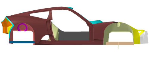

Today, many companies are replacing traditional methods of fixing composite materials – including the joining of dissimilar materials – with processes involving the use of structural adhesives. In order to enjoy the cost and production benefits of this bonding method, designers need to take into account a new set of variables:
- joint design/bond assembly;
- required assembly time;
- surface preparation/bondline thickness;
- thermal expansion of dissimilar materials;
- cost effectiveness; and
- yield stress and desirable failure mode.
Joint design/bond assembly
Adhesive joint design is the first variable to evaluate. Effective bonding is highly dependent on the surface of the substrate, the environment, and understanding the stresses applied to the joint.
The three basic types or stresses are:
- tensile;
- shear;
- and peel.
Tensile stress Tensile stress is applied only in an ideal assembly application. Forces or loads are elongating the entire adhesive area in a uniform direction without any element of peel. This is rare since the nature of the bonded assembly will tend to bend and flex, creating some peel stresses.
Shear stress Another common stress is that due to shear. Shear stress testing will provide useful information for the designer. This stress type will inherently cause separation in either the adhesive or the substrate (delamination or breakage) because forces are pulling in opposing directions across the adhesive bond. Lap joints are applicable when bonding two flat similar or dissimilar substrates.
Peel stress Peel stress is the last stress type to evaluate. Typically, peel stresses can generate within rigid or flexible substrate materials when tested. Forces at one edge of the bonded joint can cause failures due to the adhesive separating and propagating across the adhesive bondline. Peel strengths are typically lower than shear strengths because the point of failure is limited to the edge of the bond and less force is required to propagate a failure once initiated. Hence, an effective adhesive joint is created when the bonded assembly is reacting to shear stresses while peel stresses are eliminated. If peel stresses cannot be avoided, evaluate or choose a more flexible adhesive with the capability of enduring applied peel stresses
The main design guidelines to be considered when designing an adhesive joint include:
- maximise shear/minimise peel and cleavage;
- maximise compression/minimise tensile; and
- joint width is more important than overlap length.
Assembly time
With increasing demand for high volume and high speed production, the component assembly time is critical. One question that has to be answered when using an adhesive is how much time is required for applying the adhesive, joining the substrates, and clamping the bonded joint?
Structural adhesives will offer various working times at room temperature to achieve this goal. Working time is considered the period of time one has to join two similar or dissimilar materials to ensure an effective bond.
This period of time may increase or decrease depending on the adhesive system used, ambient temperature and the environment. Some two-part structural adhesives are room-temperature cured products and the reaction time is affected by temperature. Faster fixture time adhesives can cut some conventional assembly times in half.
Once the working time is established, the designer should know or understand the developmental strength of the adhesive. This can be assessed through physical testing. The relative fixture time is the period of time for which the bonded joint needs to be clamped or fixed prior to moving the assembly. By this stage, the designer should recognise which current assembly procedures can be eliminated by the use of an adhesive, and how much time is saved or gained in assembly.
Surface preparation/bondline thickness
Adhesives are an effective joining method since more physical loading can be distributed across a broader surface area in comparison to conventional rivets and fasteners. Structural adhesives are designed for excellent surface adhesion and bonding is highly surface dependent. However, surfaces may change due to the chemistry of the base material, the surface contaminants, the moulding or processing conditions, and the release agents used in the moulding of composite parts.
Some structural adhesives are mass dependent and require enough adhesive material to react and cure properly. Consequently a nominal bondline thickness is advantageous to a designer. There are a few ways to create a bondline thickness.
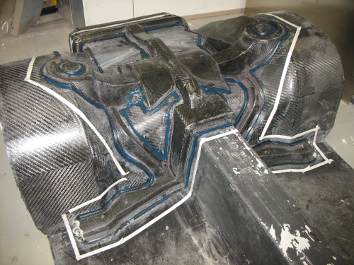
For moulded composite parts, bondline thickness can be created prior to bonding through designed presets in the mould with stand-offs or ’dimples.’ If there is no feasibility to create a tolerance for an adhesive bondline within the mould, then simple measures can be just as efficient. Small plastic washers or thin plastic spacers can be used to establish some thickness.’
When applying pressure to join similar or dissimilar materials, pressure should be significant enough to visibly see adhesive flowing from the sides of the bond area. If excessive pressure is applied to the bonded joint without any bondline thickness controls, the manufacturer can run the risk of ’starving’ the bondline. This occurs when the majority of the adhesive is squeezed out of the bond area without a significant amount of mass to cure properly. The result of starving a bondline is usually a weak bonded joint that lacks the full adhesive physical properties.
Thermal expansion
Another design variable to consider, especially when bonding two dissimilar materials, is the difference in thermal expansion. How the two materials accept and transfer heat will be different, due to their different densities. Bonding temperatures and environmental conditions may always vary. So, the coefficient of thermal expansion is a constant variable that should not be ignored. However, this constant usually is less of an issue when using structural adhesives with high flexibility and elongation. When the proper adhesive is selected, the cured structural adhesive will be able to resist and compensate for the stresses created when dissimilar materials are exposed to various temperature conditions.
Cost effectiveness
The strength of the final assembly will depend on an effective joint design, adhesive system, and how well physical loads are distributed across the assembly. To answer how well physical loads are distributed, the designer should maximise adhesive coverage. Also, the adhesive joint design should allow for maximum surface area.
When bonding, the amount of adhesive coverage or size of surface area will affect the strength of the assembly and its ability to accept higher physical loads. The greater the surface area, the greater the bond strength. The surface area will be based on the length times the width of the adhesive coverage. A depth or height based on bondline thickness should be established for a structural adhesive. A uniform bondline thickness can be critical and will assist in gauging adhesive performance.
When replacing conventional joining techniques with structural adhesives, the following calculations must be performed to ensure the design would be adequate.
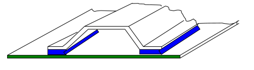
As an example, consider a flange on a composite assembly shown in Figure 1. For this case, consider a 25 mm wide flange with constant bondline thickness. As far as this study is concerned, we will consider changes in the flange width. These computations are based on width changes (flange width), since it is easier for a composite fabricator to change the mould flange dimensions than it is to change mould tolerances to control bondline thickness. The following section will utilise the data from experiments performed on conventional marine putty in comparison to a structural adhesive when bonded to a composite material. The data will then be normalised to present the differences in the systems performance.
Tensile strength For a 25 mm by 25 mm bonded assembly, the ultimate tensile load for the marine putty would be 10.3 N/mm2. The failure load for the structural adhesive with a 25 mm by 25 mm bondline is 17.2 N/mm2. The adhesive bondline width that will give a failure load of 10.3 N/mm2 is calculated by the following formula:
Tputty = 10.3 = 0.6 Equation 1: Normalised tensile stress formula T adhesive 17.2 Hence, for the adhesive to fail at the same load as the putty, the overlap width will need to be 25 mm x 0.6 = 15 mm (0.6 inch).
Lap shear strength For a 25 mm by 25 mm bondline, the ultimate lap-shear load for the putty would be 3.4 N/mm2. The failure load for the adhesive with a 25 mm by 25 mm bondline is 8.5 N/mm2. The adhesive bondline area that will give a failure load of 3.4 N/mm2 is calculated by the following formula:
t putty = 3.4 = 0.4 Equation 2: Normalised lap shear strength t adhesive 8.5
Hence, for the adhesive to fail at the same load as the putty, the overlap width will need to be 25 mm x 0.4 = 10 mm (0.4 inch).
Only two stress values have been tested. For a true estimate of necessary flange size, these equations should be applied to cleavage peel along with impact stresses for total size reduction. Even though the normalised tensile strength is the highest ratio between the putty and the adhesive, the normalised lap shear strength will be a benchmark for most designs. A designer should also account for normalised peel and impact strengths for a complete assessment.
According to the complete data, the designer can reduce the width of the flange (for the same bondline thickness) by 60%. This will satisfy all the load cases. It is recommended that a safety factor of 2.0 be introduced. This gives a 30% reduction in the width of a flange if the manufacturer were to change from putty to the structural adhesive. This not only reduces costs in composite manufacture but also adhesive usage.
Yield stress and desirable failure mode
One of the last joint design variables to verify is yield stresses of the bonded assembly and failure modes. What is required to qualify this adhesive and implement it to the current application? Physical testing on the bonded joint is required to analyse and confirm the mode of failure. Resulting failure modes and stress values achieved are valuable tools for the designer or manufacturer. This information will serve as a benchmark for final assembly load requirements.
The key is to test the bonded joint in a manner that resembles the actual bonded assembly. Once tested, failure modes can be evaluated. Generally, adhesive test failures will consist of adhesive, cohesive, and substrate failure modes. Other failure modes do exist, but are surface related. Engineering software programs are often used in this process as well as earlier stages to assist in identifying high stressed areas. They can also design in appropriate variables such as substrate thickness.
Conclusion
Structural adhesives can reduce costs by allowing bond areas to be reduced whilst maintaining the same load bearing capabilities.
In order to realise these benefits there are variables that need to be considered when changing from the more traditional methods of fixing composite materials to the use of modern structural adhesives. These variables have been outlined in this article.
In summary, when designing joints, we need to consider four key areas:
- What type of stress is applied to the joint? Shear and compression must be maximised while peel and tension need to be minimised.
- We must take into account the time required to apply and assemble the substrates.
- The surface condition needs to be consistent and the bondline must be of sufficient thickness.
- Finally, it is important to verify yield stresses and failure modes.


