


The vacuum infusion process is becoming more widespread within the composites industry. It is already commonly used in the marine sector and wind energy.
In marine, hulls are regularly manufactured from 6 m to 40 m as well as decks, floors, trays and other large components where strength and weight are important. However, the process is not limited to marine and can be used in all other market sectors, in particular construction and land transport for the manufacture of most large structures.
Vacuum infusion can be used for both one off mouldings and regular production but due to the preparation time required it would not normally be used for more than one small moulding per day per mould. Larger mouldings such as boat hulls would have a much longer cycle time.
One specialist area for vacuum infusion is to manufacture low smoke fire retardant mouldings for building and train applications using speciality filled resins (such as Scott Bader’s Crestapol range) that are difficult to process by other methods.
Benefits of vacuum infusion
| The reduction of styrene emissions will help moulders to meet any reductions in permitted styrene levels in the future. |
There are a number of reasons why vacuum infusion is being used more regularly in composites but the two main drivers are a dramatic reduction in styrene emissions and the ability to produce a better consolidated and stronger laminate. The reduction of styrene emissions will help moulders to meet any reductions in permitted styrene levels in the future.
Figure 1 shows typical styrene emissions for a laminate made by either hand lay-up or infusion. Vacuum infused laminates show better consolidation and strength as there should be no air in the laminate and the glass content will be much higher. The higher glass content means that for the same glass weight per square metre the laminate will be thinner with infusion as compared to hand lay-up and this can lead to a reduction in stiffness.
Moulds for infusion
Vacuum infusion can use the same moulds as for hand lay-up but with some modification. However, it is essential that the mould itself is in good overall condition as any cracks in it could cause a vacuum leak and therefore compromise the process. The modification necessary is to add a 150 mm wide flange around the perimeter of the mould; this will be used to set up the vacuum channel for the infusion.
It is possible to use split moulds within the process but extreme care needs to be taken to ensure that the joints are vacuum tight. It is recommended that when first investigating the vacuum infusion process that experience should be built up on single-piece moulds.
Resin selection
The resins used for infusion should be ones specifically designed for the process. There are a number of options available and they cover all types of resins such as ortho, iso, DCPD and vinyl ester. It is important that the resin chosen will give the geltime required to fill the mould as this can be quite long.
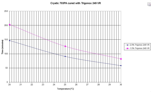
Figure 2 shows a typical gel time graph for an infusion resin. It must be noted that the graph shows geltimes at differing temperatures but in practise it is recommended that the infusions all take place at approximately the same workshop temperature in order to get consistent results.
Infusion resins have a low viscosity, typically 100-200 cps and they are non thixotropic. Thixotropic hand lay resins should not be used as they will give very slow flow.
It is also recommended that the peroxide used to cure the resins is one that uses vanishing red (VR) technology as colour change systems in the resin do not work consistently. The use of a VR peroxide will ensure that it is obvious that the resin is catalysed as any mistakes cannot be corrected.
Reinforcements
The reinforcement used in vacuum infusion tends to be different to hand lay-up. It is important that the glass drapes well as it will be necessary to dry fit it to the mould and it is essential that it conforms to the mould shape and can be easily pushed into corners.
The most common glass used in vacuum infusion is a combination mat which has a layer of chopped strand mat stitched to the surface of a multiaxial fabric. Other glasses commonly used are combination mats without chopped strand mat (CSM), and woven roving.
When selecting glass it is important to consider both the design requirements of the laminate and the aesthetics of the finished part. For the best surface finish the glass should be as smooth as possible with no gaps between the strands. Where the glass needs to be pushed into corners it is often better to use a number of layers of lower weight glass rather than one very heavy one. If there is bridging in corners then this can lead to resin race tracking and poor fill.
As the glass is laid into the mould dry a method has to be used to keep it in place particularly on vertical surfaces. There are two options for this. The first being to use adhesive backed glass where there is a layer of pressure sensitive adhesive over the whole surface which when supplied has a release film to protect it. This film is stripped off immediately prior to placing the glass in the mould. The second option is to use standard glass fabric and hold it in place using spray adhesives developed for the infusion process.
Core materials
Foams can be used within the infusion process and these are normally polyvinyl chloride (PVC), styrene acrylonitrile (SAN), polyurethane (PU) or polyethylene terephthalate (PET) similar to those used in hand lay-up but specifically manufactured for infusion. It is essential that only closed cell foams are used as any open cells would simply absorb resin when under vacuum.
In order to ensure the flow of resin around the foam they are normally supplied with predrilled holes and a grid of surface grooves on one surface. These grooves are placed away from the mould surface and will act as a distribution system for the resin. This type of foam can be supplied as both flat sheet and scrim backed for more complicated geometry.
Vacuum bagging materials
There are a number of specific items required in order to make the infusion cell.
The film used to make the bag should be one specifically made to be used for infusing the resin selected. These films are supplied in a wide range of widths and the size selected should be wide enough not to need to have any joints. This film will be held in place using vacuum bag sealant tape (bagging tape). Once again there are a number of versions of this and the selection will need to take into account the resin used, the ambient temperature and any resin exotherm.
The resin is normally introduced into the moulding through a resin feed which goes through the bag and this feeds into a distribution system which commonly uses spiral tubing. This tubing is normally wrapped in a flow mesh to aid flow.
Once resin is in the mould then it will need to flow outwards and this is either achieved with the grooves in the foam, as previously mentioned, or by the use of a flow mesh which covers the surface of the monolithic parts of the laminate. This flow mesh should not go to the extremities of the laminate as this can lead to resin getting into the vacuum channel.
Flow mesh can be very difficult to remove from a cured moulding and therefore a peel ply is often used between it and the glass. This peel ply is normally applied over the whole surface including any foam areas so that once peeled off the surface has a good aspect. Peel ply also offers the opportunity to get better secondary bonding of the infused laminate if peeled off immediately prior to bonding.
The vacuum channel mentioned above is made using spiral wrap and inlet similar to that used for the resin.
The process
The actual vacuum infusion from start to finish involves a number of steps.
Mould preparation is normal and a gel-coat is applied.
This is then normally followed by a hand lay-up skin coat using at least one layer of 300 or 450 g CSM. This skincoat has two uses. Firstly it will ensure that the first layer of the laminate should not have any voids between it and the gel-coat, and secondly it will reduce the radius of any corners allowing the dry glass to be fitted more easily. Care should be taken to ensure that no splashing occurs onto the flange.
Once the gel-coat and skin coat have gelled a band of bagging tape should be applied to the outer perimeter of the flange.
The first layers of glass are then applied dry on top of the skin coat and held in place with the adhesive systems previously mentioned. The glass must be pushed into all corners so that there are no voids. If foam is to be used this can be positioned at this point and where possible if there are any joints then the surface grooves should match up. It is best to chamfer the outer perimeter of the foam in order to make subsequent glass fitting easier. More glass can then be applied as necessary.
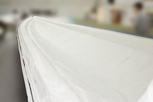
Figure 3 shows a boat hull being prepared for vacuum infusion, with the glass loading completed.
The spiral wrap vacuum channel is then fixed close to the bagging tape and held in place using small strips of tape. Dependant on the size of the moulding a number of vacuum take off points will be needed and as a minimum two should be used at opposite ends of the moulding.
Peel ply can then be fitted over the total surface and should finish under the vacuum spiral. Peel ply should be the only material that links the glass to the vacuum and will act as a resin brake.
Flow mesh should be applied to all monolithic areas of the laminate and should overlap onto any foam sections. However, the flow mesh should not go to the edge of the glass pack but should stop approximately 150 mm short. This should ensure a more even flow at the end and reduce the possibility of resin entering the vacuum channel.
The resin flow spiral channels are then positioned on top of the laminate. These should be wrapped in flow mesh to ensure rapid flow from the channel. The positioning and length of the flow channels will need to be designed so as to give an even flow in all directions. With larger mouldings a number of flow channels will be needed as the rate of fill will slow over distance and it is recommended that they should be at maximum 1 m spacing.
Once all the above is in place the land area should be checked to ensure there are no loose fibres as these can affect the vacuum integrity.
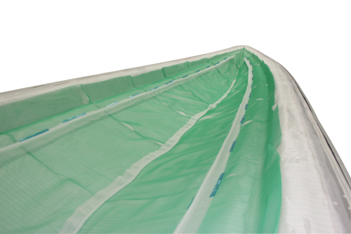
Figure 4 show the flow mesh and resin feed channels in place.
| Extreme care needs to be taken with the film to ensure that it cannot be damaged. |
The next step will be to prepare the film and dependant on the complexity of the moulding this should be approximately 1.5 times the length and width of the dimensions of the mould. Extreme care needs to be taken with the film to ensure that it cannot be damaged as finding small holes in the middle of the film can be difficult.
It is recommended that the roll of film is held on a rack which can be taken to the mould and then unrolled directly. The bag should then be cut at the appropriate length and roughly fitted onto the mould. Any blades and sharp objects should not be left in proximity to the mould in order to ensure that the bag is not punctured.
The bag is then fitted to the mould by slowly stripping off the release film from the bagging tape and smoothing the film onto it. It is essential that there are no creases in the film where it is fitted as these will lead to leaks. In order to ensure that there is sufficient film to take up the full shape of the moulding it is necessary to introduce pleats. These are needed to give enough film to cover any design features on the moulding as the overall length of the mould will be less that the distance over all the contours. Regular checks need to be made of the film so that there is an excess in all areas to avoid any possibility of bridging.
Once the film is fully fitted the vacuum lines can be connected, once again ensuring that there are no creases in the film at this point. The vacuum can then be applied and as the air is being removed the bag needs to be located correctly to avoid any bridging on corners.
Please note that it is essential to have a catch pot between the mould and the vacuum pump to stop any possibility of resin entering the pump. Vacuum pumps can be slow in removing the air due to their throughput and the initial removal can be helped by using a vacuum cleaner. Once the bag is evacuated then checks need to be made for any bridging or poor fit, if found, the vacuum needs to be released and the film moved as required and then vacuum reapplied.
| The bag needs to be checked for leaks ... Any leaks found need to be repaired. |
The vacuum level used should be greater than 0.8 bar vacuum and as near to 1.0 bar as practical.
The bag needs to be checked for leaks and there are a number of leak detectors on the market. Any leaks found need to be repaired.
When no further leaks can be detected a vacuum drop test should be carried out. This means that there should be a vacuum gauge fitted to the bag and the vacuum pump clamped off. The vacuum drop needs to be as low as possible. An acceptable level of drop would be below 0.1 bar in 15 minutes but the actual level would depend on the mould size. If the drop is too large there will be a leak somewhere and this will need to be found and rectified.
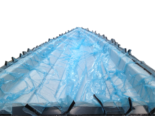
Figure 5 shows the bag under vacuum to test for leaks. When the bag is vacuum tight the resin feed pipes can be connected and once again these should have no creases in the bag in the area. The resin feed pipes need to go from the feed point to the supply container and should be clamped off prior to fitting to avoid vacuum loss. The end to be inserted into the bag should be cut to a point and wrapped with bagging tape at approximately 25 mm from the end. The point is then pushed through the inlet port which will pierce the bag and the bagging tape will remake the seal. These areas should be checked for leaks with the leak detector.
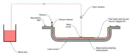
Figure 6 shows the complete vacuum infusion set up.
The actual infusion can now take place. The catalysed resin needs to be put into a suitable container which should be positioned below the level of the mould. The closed resin feed pipes should be submerged in the resin and held in place.
| It is normal practise to open the feed lines in sequence. |
It is normal practise to open the feed lines in sequence; the one in the centre of the moulding should be opened first. This will allow the resin to flow and other feed lines should only be opened when the resin flow has reached them as if opened too early there is a possibility of resin block off to some areas.
It is essential to keep the resin container topped up with resin because if any air gets into the moulding then it could be ruined.
During the infusion careful watch needs to be made in order to rectify any leaks observed as soon as possible.
When the mould is full there should be minimal resin getting to the vacuum channel and if this is the case the resin feeds can be closed and the moulding left under vacuum. The vacuum needs to be left on at least until the resin has gelled and exothermed but preferably overnight.
Options
The above process covers the basic method of carrying out vacuum infusion but there are other options available. In some cases it is impossible to use the flange area on a mould. If this is the case the vacuum channel can be applied directly onto the dry glass using specialist vacuum breather pads. The use of these would be outside this article.
A further option is to inject the resin directly into the bag rather than the vacuum pulling it from a container. Composite Integration has developed a system which allows this by carefully monitoring the pressure within the bag and then adjusting the injection rate to give even fill. This process can speed up the infusion and reduce waste resin. In conclusion, vacuum infusion can be successfully used by most composite manufacturers as it is a method of producing high quality mouldings with minimal styrene emissions. The process does however require training for the operators and care in application. Most operators rise to the challenge of the new process as the benefits become apparent. ♦
Further information
Trevor Osborne has recently retired from Scott Bader where he worked all his career. His last role was as Composite Technical Support Manager based in the UK where he supported Scott Bader customers both in the UK and globally.
This article will be published in the January/February 2014 issue of Reinforced Plastics magazine.
The digital edition of Reinforced Plastics is distributed free of charge to readers who meet our qualifying criteria. You can apply to receive your free copy by completing the registration form.


