Deploying fewer structures for a given amount of power in the tough marine environment is one way of ensuring that offshore wind can be competitive. Moreover, the stronger and more constant winds available offshore will keep the larger machines turning. Hence, we are witnessing the emergence of a new breed of megaturbines in the 5-10 MW category.
Currently, a handful of suppliers including Clipper Windpower, Multibrid, Sway, REpower, Enercon, Mitsubishi Wind Energy and American Superconductor (AMSC) are breaching the psychological 5 MW barrier with their latest projects, a number of which will even approach 10 MW. Where these producers lead, others will follow.
The Clipper giant
Clipper Windpower Inc, headquartered in California, USA, but building a major presence in the north east of England, has its sights set on a 10 MW giant, primarily for offshore deployment.
Because of the UK's burgeoning offshore market and rich wind resources, Clipper is basing much of the activity for its 10 MW Britannia offshore wind turbine project in Britain, in particular at the National Renewable Energy Centre (Narec) at Blyth, Northumberland, and what will soon be a new wind turbine blade production facility near Newcastle.
The UK Crown Estate, which has encouraged wind energy with its massive Round 3 concessions for wind farm development in 9 coastal zones around the UK, has undertaken to purchase the prototype. German developer wpd Offshore GmbH has included the Clipper 10 MW technology in its bid to implement a 1350 MW project in the Hastings Zone.
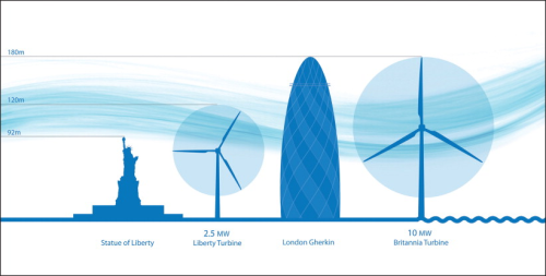
Clipper's10 MW Britannia is of conventional horizontal axis, three-blade rotor form since this is well understood and proven. The 175 m high (with rotor) machine will be assembled at the Narec site and the 72 m long rotor blades will be manufactured at the new factory alongside the River Tyne near Newcastle.
Riverside assembly is practically essential as the immense 30 tonne wind turbine blades and other components have to be shipped, because transporting them overland would be impractical.
The company is investing some £25 million in the new 43,000 m2 blade factory, now under construction on reclaimed riverside land. According to David Still, Managing Director of subsidiary Clipper Windpower Marine Ltd, the prototype should be ready within two years and should, he expects, lead to series-manufacture.
Still says: “It's an exciting time for renewables in the UK and it is great to see the factory start to take shape. We're looking forward to starting blade production towards the end of this year.”
Blades and other major wind turbine components will be tested at Narec, and Clipper — which has received some £4.4m of British Government funding for the project — is reportedly considering setting up a separate facility to assemble gearboxes and nacelles.
David Brown Gears will have an important part to play in developing and supplying the Britannia's gear system. Clipper's Still prefers local sources due to the sizes and weights of the components involved. And, as he aptly observes: “To be successful, we need a supply chain that will grow with us.”
Clipper is guarded about technicalities, but it is fair to assume that its 10 MW machine will, where possible, have a similar architecture and design philosophy to its existing 2.5 MW Liberty wind turbine, which has established a considerable track record.
Liberty is a variable-speed machine in which power electronics convert the ‘wild’ output to the frequency and voltage levels required by the grid. Clipper is proud of the Quantum Drive™ power train used in this product.
Wind turbines in the multi-megawatt category generally have rotors that rotate slowly to limit tip speeds, but they develop high torque. Managing the latter is a challenge, which Clipper meets by splitting the torque four ways, the rotor directly driving a large planetary gear which is geared to four permanent magnet generators.
The company says that this arrangement eases point loads, reducing major component failures and extending operating life. The redundancy accorded by the presence of four generators ensures that power output is maintained even through a generator outage.
Reliability, always important, is at an absolute premium offshore where service intervention can be extremely costly. Designers therefore favour simple architectures with low part counts. In this respect, Clipper is likely with its 10 MW machine to follow the precedent it has set with Liberty, which is claimed to have about half the number of parts in its control system as are found in today's ‘standard’ wind turbines.
The permanent magnet generators used are simpler than the more conventional variable-speed alternative of doubly-fed induction type and require less maintenance. There are no brushes to replace, no slip rings, no need for a slip clutch between the gearbox and generator, and operation is not marred by the stray currents that can lead to pitting and bearing failures in conventional generators.
Clipper argues that taken in combination with the Liberty electronic converter, the permanent magnet generators are grid-friendly. Advanced power electronics secure effective variable speed control and a three-second voltage ride-through capability, ensuring that the system meets stringent grid standards, both existing and planned.
The wind turbine's power train is protected by a health and condition monitoring system which, by monitoring trends in operating parameters, oil debris and vibration signatures, can detect machine wear and incipient damage that might indicate a future need for unscheduled maintenance. Such predictive capability allows operation to be modified to minimise further stress until such time as the matter can be attended to within a scheduled maintenance period.
Very tall structures can be expected to attract lightning, but Liberty is able to ride through lightning strikes thanks to receptors at the rotor blade tips that are connected through brushes at the hub and via the tower to the ground.
To facilitate scheduled maintenance, the Liberty wind turbine has multiple inspection ports, including man-sized ports in the nacelle housing to provide access to the hub interior; a two-person service lift to speed the journey to the nacelle, and an on-board hoist. The latter can be used to change out generators, high speed gears, yaw and pitch motors, avoiding the need to field a separate crane.
It remains to be seen to what extent Clipper can retain the architecture and features proven in Liberty, while adapting it to the scale of the much larger 10 MW wind turbine. The electronics and control system will have to handle much higher power levels, in some cases exceeding the capability of power electronic components currently available, so further innovation may be called for.
At the rotor, the company will be keen to ensure that the lessons learned after some earlier issues with rotor blades for Liberty machines are carried through to the design of the immense composite blades required for Britannia.
| "To be successful, we need a supply chain that will grow with us." |
| - David Still, Managing Director of Clipper Windpower Marine Ltd |
Other challenging issues will include the productionisation of one of the largest wind turbines yet contemplated, forging a supply chain able to meet Clipper's exacting requirements, assembling the machines onshore and then shipping them to their offshore operating locations, erecting and commissioning them.
Swaying towards 10 MW
Clipper Windpower faces commercial challenges too, and could be racing Norwegian interests to field the first 10 MW offshore turbine. Energy and engineering firms Statoil, Lyse, Inocean and Enova are collaborating in the Sway consortium which is targeting a wind turbine of similar scale to Britannia, with a 145 m diameter rotor.
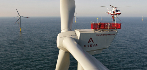
The project has other similarities to Clipper's — not least the use in the chosen Areva Multibrid turbine of synchronous permanent magnet generators, along with a compact hybrid power train architecture. But there is a fundamental difference; instead of being installed on heavy foundation structures placed on the sea bed, each Sway turbine will be deployed on a floating tower attached to the sea bed with tethers and anchors.
A Sway tower will be counterweight ballasted so that it stays more or less upright, like an angler's fishing float, simply swaying gently in response to sea disturbance.
This solution, says Sway CEO Eystein Borgen, is therefore suitable for deeper waters where floating foundations will be much more economical than fixed foundations. This follows, Borgen points out, from the so-called square-cube law under which, if the rotor diameter is doubled (and therefore the swept area and power production are increased four-fold), the weight and cost of most of the turbine and tower/foundation components increase eight-fold due to the length increases in all three spatial dimensions.
A structural concept based on buoyancy should circumvent this increase. Offshore wind is likely, Borgen contends, to follow the example the oil and gas sector has set in adopting floating platforms for deep water, rather than the bottom-fixed structures it previously adhered to.
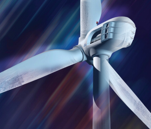
When it comes to minimising head weight and volume so that more powerful wind turbines can be carried on given tower and foundation structures, the Sway/Multibrid solution has resemblances to Clipper's. In particular, the power train architecture is mid-way between direct drive, with its associated large-diameter generator, and the conventional multi-stage geared drive requiring a substantial gearbox.
In a technology licensed from originator Aerodyn Energy Systems, Multibrid uses a rotor-driven planetary gear to drive one or more generators via high-speed geared power take-offs. This results in a compact drive train, as evidenced in the 5 MW model that Multibrid has developed for offshore use and is serving off the north coast of Germany.
As a result of its compact integrated slow-rotating drive system, single-stage gearing and a single main bearing (no main shaft), the M5000 has a tower head mass of just 310 tonnes, making it the lightest 5 MW wind turbine around, claims Multibrid.
The compact nature of the power train has enabled designers to produce a relatively low-profile nacelle, reducing wind resistance and structural loadings. Nevertheless, it offers ample working access for technicians. Hermetic sealing of the nacelle and hub, along with an air filter and treatment system, protects the power train from the aggressive humid and salt-laden marine atmosphere.
For Sway, Multibrid has adapted its wind turbine design to operate in downwind mode (rotor on the downwind side of the tower). This ensures that, as the tower tilts away from the wind, the rotor blades maintain their alignment with the wind when bending backwards under wind pressure.
Wire shrouds rigged from the top of the tower to an ‘A’ frame near its base on the upwind side help stiffen the tower structure — in a similar manner to the way yacht masts are braced — enabling a heavier turbine head to be carried than would otherwise be the case.
The Areva-Multibrid M5000 is one of several 5 MW wind turbines now available. Another is the BARD 5.0 turbine from BARD Engineering GmbH, a company that erected an initial research version on a tri-pile foundation in 8 m deep water off the German North Sea coast in 2008.
Like Multibrid's M5000 and similarly derived from Aerodyn technology, the BARD 5.0 has a single rotor bearing and a spherical iron main chassis. However, the BARD wind turbine model differs in having a double-fed induction generator driven via a three-stage planetary and spur gear gearbox.
Power electronics are located in the tower base rather than in the nacelle. Wind turbine construction and assembly take place at Emden, while the 1100 tonne tri-pile foundation is produced by BARD subsidiary, CSC Cuxhaven Steel Construction.
The 122 m diameter rotor features foam-cored glass reinforced/epoxy wind turbine blades weighing 28.5 tonnes each. It is designed to rotate about 20% more slowly than conventional blades, minimising tip speeds — and hence also abrasion and maintenance.
Startling scale
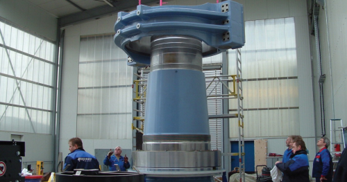
An example of the startling component scale required by megaturbines is the bearing system for the 5 MW wind turbine produced by another German firm, REpower Systems AG. This company's 5M model, standing 183 m high and with a 126 m rotor, was the world's largest wind turbine when introduced in 2005.
A number of 5Ms have since been installed, including 6 at Belgium's first offshore wind farm, some 30 km from the coast on the Thornton Bank. Sweden's SKF Group designed the twin bearing system for the 1.5 m diameter hollow cast-iron main shaft on which the 130-tonne three-blade rotor is mounted.
SKF used dynamic simulation software to design the two spherical roller bearings, which must withstand the high cyclic loads continually exerted by the rotor over a prolonged service life.
Even though designed to be as small and light as possible consistent with this purpose, each roller/bearing set weighs almost 800 kg. A research programme had to be conducted to establish the lubrication requirements for 1.5 m diameter bearings since previous roller bearing experience extended only to 500 mm diameter.
The impact of scale is even more evident in the next power step up, towards 7 MW plus. As an official with yet another German company, Enercon GmbH, has observed, when wind turbines reach the size of Enercon's latest and largest, the E126, there is conceptually little difference between a wind turbine and a conventional power plant.
With its 126 m diameter rotor, the Enercon 126 can deliver more than 7 MW though it is initially rated at 6 MW. Erecting an E126 on land, as Enercon has done for the Belgian wind farm Estinnes, calls for an erection crew about twice the size of a typical 2 MW installation team. Bolting the sections of each segmented wind turbine blade together, alone, takes three workers a day and half per blade. A segmented design was adopted because of the impracticality of transporting complete blades by road.
A critical part of the erection procedure, lifting the 22 m long nacelle to the top of the 131 m high tower, requires a crane of gargantuan proportions. In this case, Belgian heavy lift specialist Sarens built an enormous crawler crane to Enercon specifications.
This can raise its hook to a height of 230 m and can manage a complete motor and generator assembly in a single lift. It is dismountable into sections suitable for road transportation, although moving all the sections reportedly requires up to a hundred special heavy-duty truck loads. It is not clear to what extent different lifting arrangements would have to be adopted for an offshore deployment.
The E126 tower is, likewise, assembled from sub-elements. Each tower is made up of 35 tapering concrete rings with diameters ranging from 14.5 m at the base to just over four metres at the top. The lowest rings are made in three 120° segments, with others further up the tower being produced in two 180° halves.
A yaw bearing and 8 yaw motors are at the top of the tower while power electronics are contained within a two-level structure at the base.
Enercon has favoured a direct drive solution for the E126 wind turbine, enabling it to dispense with a main gearbox altogether. Chief advantage of reducing complexity in this way is higher reliability, gearbox issues being a common cause for unscheduled maintenance.
However, the large-diameter generator that is the consequence of a gearless design takes up the entire width of a large nacelle. Two working platforms provide access to the nacelle for technicians, whose journey to the top is assisted by a 100 m elevator, though a certain amount of ladder climbing is involved too.
Does size matter?
The rise in mass and size that accompanies growth in rated power is seemingly inexorable. But one company, at least, believes that it does not have to be so.
AMSC claims that it can almost halve the weight of a generator of given power by exploiting the phenomenon of superconductivity. Certain materials, when cooled to cryogenic temperatures, lose virtually all resistance to electric current. It is possible to make some of these materials into wire.
Using such superconducting wire in the windings for electric motors and generators greatly increases their power for a given size.
AMSC, which is already established in the wind energy field through its subsidiary Windtec, has entered the 10 MW arms race with its SeaTitan, a direct drive wind turbine design featuring a generator equipped with superconducting windings.
This has resulted from a collaboration with TECO-Westinghouse Motor Co that began almost three years ago, with funding assistance from the National Institute of Science and Technology's (NIST) Advanced Technology Program.
Dan McGahn, Senior Vice President and General Manager of AMSC, argues that if a nacelle design can be produced that doubles the power of a 5 MW system while being similar in size, one can leverage a lot of what is being developed for 5 MW systems.
For instance, processes and logistics involved in fabricating, moving to site and installing 5 MW systems can be utilised for 10 MW superconductive systems. Nor does 10 MW have to be the limit. McGahn believes that the ultimate limit will be imposed by the length of wind turbine blades that can be supported and how high structures are allowed to go.
Should SeaTitan enter production, perhaps by the middle of the decade, this is likely to be undertaken by partner companies that AMSC Windtec is already used to working with, for example Hyundai and Sinovel. The latter, a Chinese company, is planning to build a 5 MW wind turbine using existing technology, and some of this might readily transfer to a new 10 MW superconducting model.
10 MW wind turbines are so much larger than what utilities are used to that the US Department of Energy (DoE) has teamed up with AMSC to study to what extent such machines are practical. Working with Windtec, the National Wind Technology Center of the National Renewable Energy Laboratory (NREL) is evaluating the costs and economic viability of a full 10 MW class superconductor wind turbine.
Also in the USA, NREL and MIT researchers have collaborated on investigating the practicalities of integrating wind turbines with floating platforms like those used in offshore oil rigs. Working with a notional 5 MW machine as their baseline, they considered whether it would be feasible to moor such units in depths of 30-200 m, such as are found some 50-100 km off the north-eastern United States.
In Europe, megaturbine research has been a focus of the UpWind project, funded under the EU's Sixth Framework Programme. Some 40 UpWind partners have, among other matters, considered ways to reduce overall wind turbine mass while also achieving the highest degree of reliability.
Spain's Gamesa and Ecotecnia have led a parallel research project aimed at halving lead times for getting very large wind turbines from initial concept to market and reducing the energy required to produce them by 30%.
Windlider 2015, so called because of its focus on machines expected to become available by mid-decade, assumed 5 MW machines in the first instance, but with expectations of extrapolating their performance to outputs of 10 MW and more. Testing of full turbine assemblies up to at least 8 MW can be carried out at the advanced wind research centre at the Centre for Renewable Energy Research (CENER) near Pamplona.
Finally, there is no certainty that the conventional ‘Danish’ three-blade horizontal axis wind turbine model will end up as the prevailing form for offshore megaturbines.
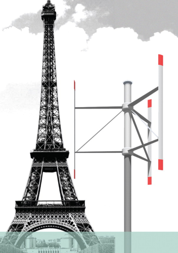
British company VertAx Wind Ltd believes it is easier to scale up its vertical axis wind turbine than a horizontal axis wind turbine (HAWT) and has plans for a 10 MW machine that it says could “dramatically lower the costs of developing offshore wind farms”.
Managing Director Steven Peace says that growth in HAWTs will eventually be constrained by practical limits on the size of the rotor and its blades. Sharing wind loads between more and smaller blades on VAWTs will, he says, overcome this, added to which the lighter, untapered blades will be easier and quicker to produce.
Slingsby Composites is working on blade development for the project. Currently, marine engineering specialist SeaRoc is considering the best way to install the VertAx machines, as they enter their second phase of development.
Time will tell how large wind turbines can ultimately become and what basic form future giants will take. Meanwhile, manufacturers are putting on their 10-league boots and starting to produce the 5-10 MW megaturbines that will stride across the future seascape.
This article first appeared in Renewable Energy Focus, Volume 11, Issue 4, July-August 2010.
