
In the 1970s there were three projects that utilised FRP pipes for power plants. Inspections after more than 22 years of service indicate that the FRP pipes are still in excellent condition.
Florida, USA
In 1978, a Florida power plant needed pipe to transport large quantities of hot water to a salt-water environment and at the same time have minimal effect on sea life. It was required that the main trunk line be 3000 ft (914 m) long by 16.3 ft (5 m) in diameter. At the end of this section, a Y connection was required to divert the hot water in two different directions into the At1antic Ocean. The two pipes that came off the Y section were to be 10 ft (3 m) in diameter and 150 ft (46 m) long. The pipe connections were to be double 0-ring, bell and spigot joints. The requirements were that the pipes be:
- corrosion resistant to salt water and soil;
- strong enough to withstand ocean and river currents; and
- as lightweight as possible to minimise installation costs. (The engineers looking after the installation preferred lightweight sections of pipe in order to utilise lower cost small cranes.)
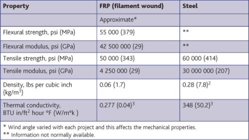
FRP is inherently corrosion resistant to salt water and most soil conditions. The mechanical properties of steel were compared to that of FRP, and these comparisons are listed on Table 1. The tensile strength of steel is slightly higher than FRP but the tensile modulus value of steel are much higher than FRP.1 Over several years, engineers have been able to design around this difference. The huge difference in density is a significant advantage for FRP.
New York State
A typical hydroelectric power facility includes a dam, reservoir, pipes or penstocks, a powerhouse, and an electrical power substation. Dams hold back a tremendous amount of water that is stored in a reservoir. Near the bottom of the dam wall is the water intake. Gravity causes the water from the reservoir to fall through the penstock inside the dam. At the end of the penstock, there is a turbine propeller that is turned by the moving water. The turbine is connected to a generator that uses the rotating propeller to generate power. After the water passes through the propeller of the generator, it goes through a tailrace on the other side of the dam where it continues to flow downstream.
In 1979, New York State had two wooden penstocks that supplied water to power plants, but because they were leaking water they had to be replaced. This lost water resulted in less than desired electrical efficiency at the power plants. The pipes that were replaced were 10 ft (3 m) and 12 ft (3.6 m) in diameter. The smaller diameter one was 5620 ft (1713 m) long and the larger one was 7808 ft (2380 m) long. One significant difference between this and the Florida project is that, in this case, the pipe was mostly buried and thus would not be subjected to any movement, except for that of freezing and thawing.
After a considerable amount of engineering considerations, which compared the advantages and disadvantages of various construction materials such as wood, metal pipes and glass fibre reinforced plastic pipe, an FRP pipe was chosen for the project. The reasons that FRP was chosen were:
- FRP has demonstrated that it is corrosion resistant to both salt and regular water. FRP has been used to carry water for many years in pipes and also it has been used successfully to manufacture marine vessels;
- FRP has been used to manufacture pressure vessels and has acquired a history of meeting high mechanical properties;
- FRP is known to be lightweight compared to metals. For example, a filament wound pipe is normally about 0.06 1bs per cubic inch (1.7 kg/m3) versus 0.28 lbs per cubic inch (7.8 kg/m3) for carbon steel;2 and
- FRP has much lower thermal conductivity values. This was important in transporting hot water from the Florida power plant to the Atlantic Ocean. The thermal conductivity of FRP is 0.277 BTU in/ft2 hour °F or 0.04 W/m °K, where steel is 348 BTU in/ft2 hour °F or 50.2 W/m °K3.
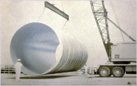
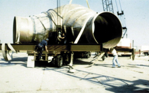
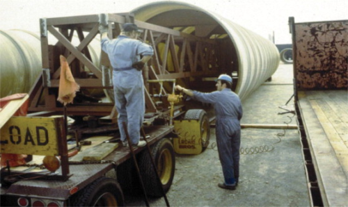
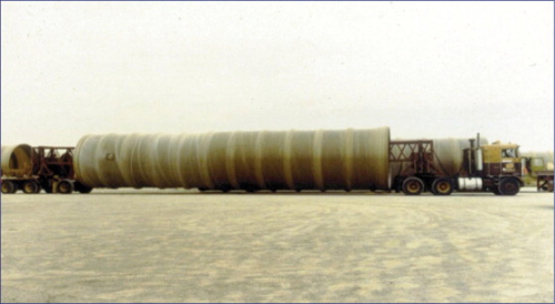
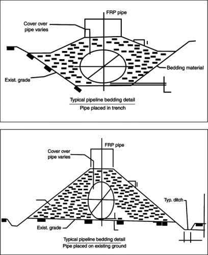
A fibreglass pipe manufacturer was chosen for these three projects. This company selected a resilient isophthalic resin and glass rovings to produce the pipe. A 50 ft (15.2 m) long section of the pipe that is being transported to the plant site is shown in Figure 1. Figure 2 shows the Y section of the pipe before installation that was to divert the hot water from the main trunk line. Two pictures of pipe being transported to the site are in Figure 3 and Figure 4. Figures 5 and 6 have two drafting diagrams describing how the pipe was buried.
The first project was completed in 1979 and the second was finished in 1980. Inspections after more than 22 years of service indicate that the FRP pipes are still in excellent condition.
The power companies asked that the exact location of their plants not be disclosed due to security concerns; thus, power plant engineers and their respective companies will not be referenced in this document.
Current status
The pipes at the Florida power plant continue to perform well, but since the pipes are always submerged they are difficult to inspect on the inside. The exterior surface is still in excellent condition. According to personnel responsible for maintenance, there have been no problems associated with the FRP pipes.
The New York penstocks have recently been inspected and in the words of the responsible engineer, the fibreglass pipes are in ‘awesome condition.’ At the same time of inspection, several rivets from connecting metal structures needed to be replaced as a result of corrosion. Unfortunately, the age of the steel pipe was not available to us.
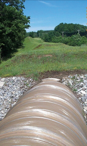
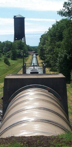
One additional fact that was brought to their attention was that the FRP was a much better insulator than metal pipe. This was evident as the inspectors walked through the pipe (when the power plant was shut down for inspection). Water in the pipe would have less chance of freezing and restricting the flow of water in the wintertime; likewise, in Florida, the FRP pipe was able to transport hot water from the power plant away from the inter-tidal area, thus minimising effect on sea life. A photograph looking up-gradient along a buried section of the pipe is shown in Figure 7. A down-gradient picture is shown in Figure 8 where the FRP connects into a steel pipe.
This article was presented at the International Conference and Exhibition on Reinforced Plastics (ICERP) 2008, which took place in Mumbai, India, on 7-9 February 2008, organised by the FRP Institute, India.
|
1. ASME B31.3-1996 Edition. 2. R.I. Roark and W.C. Young, Formulas for Stress and Strain, McGraw Hill (1975) Table 38. 3. Young and D. Hugh (7th Ed.), University Physics, Addison Wesley (1992). |


