

Composite materials have been used in the marine industry for several decades because they stand up to corrosion better than metals and they behave better structurally than wood. Composites are found in key structural applications throughout the recreational, commercial and naval industries, from dinghies to nuclear submarines.
In some cases, composites have also been used to reduce the radar signature of military ship superstructures, eliminate magnetism in minesweeper hulls (still made out of wood prior to composites), reduce weight, improve stability, and increase stiffness in lightweight racing or patrol boats (which are now being made out of high performance carbon fibres).
Despite this extensive use of composites, the marine industry has until recently shown little interest in the advanced composite engineering software tools developed in other industries, such as aerospace, automotive or, more recently, wind energy.
It may be in part because the typical design and manufacturing process is set up differently in the marine world than it is, say, in aerospace. The naval architect and the manufacturing outfit directly interact and share responsibility for the composite design specifications. Often, there is not a person or team in the design office that has been schooled in detailed composite design. Many composite marine components are considered simple enough to develop without the use of a sophisticated 3D CAD based composite design approach.
Typically, the marine industry has relied on lower priced glass fibre reinforced plastics (GRP), based on glass fibres and polyester resins. Cost effectiveness has kept the industry from moving to the higher performance and more expensive materials found in aerospace, such as carbon fibre reinforced plastics (CFRP).
However, in recent years, shipyards — military, commercial and recreational — have shown a growing interest in adopting a more productive and sophisticated composite engineering process. They have begun to evaluate the engineering software tools that have proved successful in other industries.
Improving productivity
Manufacturers of boats and ships of all sizes and complexity are seeking ways to enhance their competitiveness. Bringing their products to market faster and at less cost is critical to accomplishing that goal. Enhancing productivity is a key driver in the face of a tough economic climate and growing global competition. Reducing cycle times means lower inventories, providing more time for customisation, and improving the return on tooling use. Reducing engineering and production costs, labour costs and material costs all improve the bottom line.
Lowering the total cost of ownership and reducing life cycle costs is also a primary objective of manufacturers. Well designed composite parts show a high potential for low maintenance and easy repair. Recently great consideration has also been given to the issue of recyclability.
Improved quality in design and manufacturing supports the goals stated above. Paying more attention to the details of the design and manufacturing process enables significant time to be saved because there is less rework on the manufacturing floor, fewer errors that need to be corrected late in the process, better accuracy, and more repeatability.
Marine applications are designed for reliability in extreme weather conditions and hence carry large safety margins. Yet performance is critical in many applications. Speed and stability become the primary drivers of the design. Such is the case for racing boats, fast patrolling and special ops crafts and some fast passenger ferries. Weight reduction is also sought after for the superstructures of military and commercial ships where a lower center of gravity means improved stability and safer behaviour at sea. Minimising and accurately controlling the weight of the composite laminates enables better performance.
The benefits of composite materials
Composite materials have shown many benefits over the years, including:
- providing the ability to design the material by combining fibres and resins in different ways and by placing the fibres along preferred orientations thus reducing the weight to strength ratio;
- enabling part consolidation, thus reducing part counts, joints and fastener counts and manufacturing steps;
- providing significant weight reductions and improvements in stability by helping lower the center of gravity; and
- enabling easier application to complex shapes and compound curvature – composites are ‘drapable’ to a large extent – therefore, hulls, decks, submarine fairings are all ideal candidates for composite manufacturing.
Enhancing design methodologies
With its origins in structural design and in textile engineering, composite engineering remained more of an art than a science for several decades. It still is, to a large extent, considering the amount of manual process that goes into manufacturing most composite structures.
Yet major progress has been made over the last 15 years in the development of consistent design methodologies for composite parts and supporting software tools. In particular, powerful engineering software dedicated to the design and manufacturing of composite laminates has been developed and become the backbone of the composite design process.
Such an approach has already been adopted by several of the major commercial, recreational and naval manufacturers. However, the industry as a whole has not yet embraced this approach.
Designing success
There are a number of reasons why such software was developed and became a key ingredient of the composite engineering process. For instance, it is highly desirable that a part be manufactured as it was designed. This sounds like a given, yet if you talk to any design manager or production manager, you will find that is not the case. Changes are made after the design release, to make the part more ‘manufacturable.’ These changes are typically made on the fly, decided on the shop floor, so there is no record or traceability back to the design office. In the end, it is difficult to know for sure how different the real part is from the approved design.
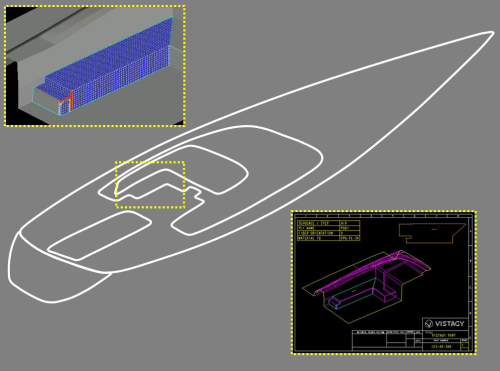
Using composite design software also allows the engineer to greatly reduce the number of changes required throughout the development process. It enables the user to rapidly record all the design changes. By creating a complete and detailed 3D composite design of the parts and assemblies early on, all the laminate, ply and core information provided to manufacturing is consistent and frozen in minute detail. Figure 1 shows an example of ply layup definition from VISTAGY’s FiberSIM® composite engineering environment. The software allows designing the ply layup, including all the details pertinent to the ply dropoffs, staggers and overlaps, specifications for ply orientations and materials.
Traditionally, the process of figuring out how to lay up the glass fibre fabric or tape inside or over the mould is not part of design. It is left to the manufacturing technicians to come up with the appropriate ply shapes and ensure that there will not be any manufacturing problems, such as wrinkling or bridging of the material in curved areas. When such a manufacturing defect cannot be avoided, weakness may ensue that can trigger cracks and fatigue failure.
Composite design software provides a means to simulate the ‘draping’ of composite plies and assesses the ‘producibility’ of the laminates ahead of time. A lot of research and development has taken place in the last decade to provide very accurate material simulation algorithms that can predict wrinkling and bridging and other defects that can occur in the manual layup process. It is now possible to know how the plies will conform to the mould before any physical prototype is built. This ability to simulate before manufacturing begins has already been providing great savings to the aerospace, automotive and wind energy industries.
Linking design and manufacturing
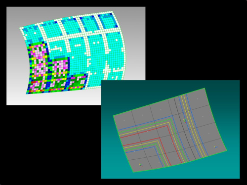
Design and stress analysis are the two pillars of the engineering process. Often, the communication between the two disciplines is not optimal so iterations are tedious and slow. The CAD world and the CAE world are known for their inability to communicate effectively. The complexity of composites poses an even greater challenge. However, good progress has been made in recent years to ensure a bi-directional exchange of composite data between composite design software and composite structural analysis software. Figure 2 shows an example of concurrent flow between VISTAGY’s FiberSIM software for design and finite element analysis (FEA) software for analysis. Zone, target laminate and detailed ply data can flow from one environment to the other to ensure faster iterations for more optimisation earlier in the design process.
One of the major benefits — if not THE major benefit — of composite design software is the direct link from design to manufacturing. By creating a complete and as-manufactured definition of the composite part in the 3D CAD system, all the data required for manufacturing can be readily exported from the design master model. The engineering release contains all the information required to make a manufacturable part.
For example, the definition of the flat patterns corresponding to the 3D plies can be exported to a nesting software or cutting machine. The 3D ply definition can be sent to a laser projection system for accurate placement of the plies in the mould. The technical drawings or ply books can be automatically generated from the master model. Beyond manual production processes, composite design model can be used to prepare data for automated deposition machine systems, such as fibre placement, tape laying and rapid material placement.
Finally, additional steps have been taken to develop more powerful design methodologies for various classes of composite parts. The ‘ply-based’ design method is typically used for automotive parts and some of the complex helicopter fairings. This is the first method devised about 15 years ago that let the designer develop the ply design. The ‘zone-based’ design method is more suited to larger parts, such as aircraft wings and jet engine nacelles. Here the definition of the composite part is driven by a patchwork-like definition of the laminate using zones and associated target laminate. Finally the ‘grid-based’ design method was originally developed for composite assemblies, such as a large fuselage section. Here the design is driven mostly by the placement of the stiffeners, either frame or stringers.
All these methods are applicable to some class of parts in the marine industry: grid-based design for hull sections; zone-based design for superstructures; and ply-based design for fairings. For example, specialised methods developed for jet engine fan blades are relevant for the development of propeller blades.
Developing a reliable process
Composite design software is rapidly becoming the backbone of the engineering process in multiple industries, including aerospace, automotive, wind energy and marine.
By developing a complete and detailed 3D CAD model of the composite part or assembly, manufacturers are able to derive many benefits, including a:
- seamless link from design to the manufacturing floor;
- quality process which stems from the accuracy and completeness of the composite master model defined with composite design software;
- prediction of potential manufacturing issues;
- concurrent design and analysis process for better part optimisation; and
- specialised design methodology for a variety of parts.
As a result, the engineering process for developing marine components is becoming more predictable and reliable. Design changes happen less often and can be processed faster and with fewer communication errors. Less time is spent on non value-added tasks and, best of all, more time is spent on actual engineering and innovation.
This feature was published in the July/August 2010 issue of Reinforced Plastics magazine.
If you would like further information about any of the issues covered in this feature please e-mail us.


