
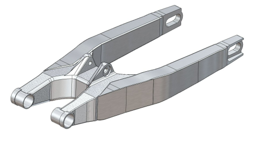
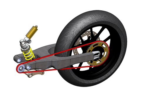
An engineering student at Swansea Metropolitan University (SMU) in Wales has redesigned and manufactured the swingarm (the main component of the rear suspension) from a Honda CRF450 motor-cross bike and made it 31% lighter.
The swingarm currently on the bike is made from aluminium and weighs 3.9 kg including bearings. The redesigned carbon fibre epoxy composite part with moulded-in metal inserts weighs just 2.7 kg, while retaining the performance capabilities of the original Honda part.
To minimise stress concentration areas and overcome various manufacturing issues, the composite swingarm was vacuum moulded in two separate sections. These were then bonded together using the same 3M adhesive system that has been used successfully in Formula 1 cars.
This swingarm composite redesign was the final year dissertation project of B.Eng. undergraduate Sven Lemmerling, supervised by Dr Owen Williams, the SMU Motorcycle Engineering Group course director. The redesign of this complex shaped motorcycle rolling chassis section in carbon fibre composite was made possible by using the Composites Modeler ply modelling and fibre simulation software developed by Simulayt Ltd (a UK company which has recently been acquired by Dassault Systèmes).
The software provided a combination of design benefits and significant production cost savings by highlighting potential production problems during the design phase and generating accurate flat patterns for faster production, lower scrap and increased productivity.
Virtual product development
It is well established that composite materials offer significant weight reduction opportunities. However, research carried out for this SMU project found little evidence of the widespread use of structural composites in racing motorbikes, with prior work being confined to a couple of specialist manufacturers. This has been attributed to the complex shapes in a motorcycle chassis and the major design and production challenges faced as a consequence. By using a specialist composites software package like Simulayt’s Composites Modeler, which is fully integrated within established 3D Computer Aided Design (CAD) packages such as SolidWorks® or Computer Aided Engineering (CAE) tools like Abaqus/CAE, it becomes viable for motorbike and other engineers to consider advanced composite materials for complex structural parts.
Composites Modeler enables virtual product development for composites by allowing the user to define the model in terms of plies in the same way that it is later manufactured. It then simulates the manufacturing process to identify and correct design flaws and manufacturing problems. Doing this at the ‘virtual’ design stage allows the design to be improved before money is spent on tooling, and can avoid the need to create costly prototypes or even throw away impractical designs.
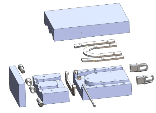
For the SMU project, SolidWorks was used to define the initial 3D CAD model of the mould, as well as the positioning of the various metal inserts. Having accurately modelled the mould and part geometry in SolidWorks, Lemmerling then went on to use Simulayt’s Composites Modeler for SolidWorks software to model the composites lay-up and generate manufacturing information. The functionality in Composites Modeler allowed him to define feasible ply lay-ups rapidly while working in the familiar SolidWorks environment.
Ply lay-up made easy
Composites Modeler allowed Lemmerling to define the composite lay-up in the same way as it would later be manufactured, on the basis of individual plies.
For each ply, faces on the 3D solid model to be covered by the ply were selected. Next, a coordinate system defining the basic orientation of the ply was identified, followed by specifying a nominal rotation angle. Finally, a start point for the draping process (i.e. where the material is first applied to the mould) was defined.
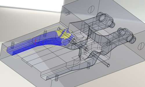
With these key inputs set, fibre simulations could be run to identify the fibre orientations and highlight potential problems. The effects of changes were immediately apparent, so the design could be improved within the CAD model.
Finally, the stacking sequence of the individual plies was defined to complete the virtual model of the composite lay-up.
According to Lemmerling, a key advantage of Composites Modeler software for a design engineer is that it can create accurate net shape flat patterns for ‘Gaussian’ surfaces, which are ‘undevelopable’ surfaces with double curvature and non-zero Gaussian curvature. For these types of surfaces, the material has to shear to conform to the surface, affecting the fibre orientations and deformation of the material. Simulayt’s fibre simulation allows instant prediction of these phenomena, allowing the designer to improve the design before it is too late. An important benefit of the fibre simulation at this pre-production stage in a project is that it ensures ‘unmanufacturable’ plies cannot be specified.
A further complication of doubly-curved surfaces is that there are infinite ways of covering the surface with fabric, so specifying the best starting point of the draping process is vitally important. Because of the speed of Simulayt’s fibre simulation, Lemmerling was able to define the most suitable starting points rigorously at the design stage so these could be used during manufacture so that the manufactured part reflected the design model.
For the properties needed for this part, MULTIPREG E722 epoxy resin with 2x2 twill 650 g/m2 carbon fibre prepreg from Amber Composites Ltd was selected after extensive lab tensile testing. Depending on the specific area of the part, combinations of 0°/90° and -45°/+45° plies were specified to provide the mechanical performance needed.
Lemmerling explains how vital the Composite Modeler software had been to the success of his project.
“It would simply not have been possible for me to succeed with this project without this Simulayt software, which was easy to use and is clearly specifically designed for fibre reinforced composite modelling. We did look at various other textile based software packages, but none of them were able to calculate the optimised fibre orientation and ply lay-up to obtain the required mechanical performance in the final moulded carbon fibre epoxy component.”
Overcoming design and production problems
The fibre simulations highlighted areas of excessive shear resulting from the draping process, allowing the designer to optimise the ply shapes and fibre orientation. The key benefits in being able to highlight problem areas at the ‘virtual’ CAD stage are firstly, a significant reduction in the overall project design time, and secondly, the avoidance of costly design errors. Without Composites Modeler, these design errors would not have been detected until after mould tooling and parts had been produced.
For the SMU project, this proved invaluable in identifying very early on the need to redesign a critical part of the initial swingarm design around the suspension mounting lugs. In order to lay up sufficient plies at the base of the lugs, the entire design approach was modified to reflect the opportunities and restrictions of advanced composites. This change resulted in a different split line being incorporated in the mould to enable a sufficient number of plies to be laid down in this highly stressed area.
As Composites Modeler is fully integrated within the SolidWorks CAD programme, the late stage design modifications were automatically recalculated throughout the whole design tree. By identifying the problem at the design stage, considerable effort and cost were saved.
“Using the Simulayt software, Sven was able to proceed to the manufacturing stage of this swingarm project with a high degree of confidence that the final moulded composite part would have the mechanical performance required for the application,” notes Dr Williams, who approved the software for this project.
Net shape flat patterns
Traditionally, rough oversized flat patterns were created manually by a moulder using paper. The paper patterns were then digitised and exported to a cutter. When the plies were laid up in the mould, any excess material was trimmed and usually scrapped. The more complex the shape the greater the inefficiencies and scrap wastage, which was prohibitive for intricate parts. Now, a key benefit of the Composites Modeler software for manufacturers is that it now removes the restrictions of traditional methods by taking 3D CAD data and immediately calculating accurate two dimensional (2D) net shape flat patterns for dry reinforcing fabrics and resin-impregnated prepregs.
This 2D data can be exported from Composites Modeler in a standard DXF file format into a 2D drawing package to make very precise templates. Using the templates, accurate net shaped flat patterns for the plies can be cut manually, minimising trim wastage. Alternatively, for larger manufacturers, production efficiencies can be fully exploited as the 2D flat pattern data can also be used to programme automated cutting machines to mass-produce kits of plies. These flat pattern shapes can be ‘nested’ manually or automatically before cutting to optimise usage of expensive raw materials.
Cost saving benefits
While not so critical for a university research project with low production volumes, by using the Composites Modeler software, many OEMs and independent composite convertors have seen significant overall cost savings. A large number of design projects have become commercially viable due to the faster flat pattern production, lower trim scrap and overall increased productivity.
Based on comparisons between using the traditional manual flat pattern paper method versus using the Composites Modeler software, ply production times can be reduced by over 75% with 15% less trim scrap. This means that a composite part fabrication which needed 50 hours labour time for flat pattern making and laying up and using £20 000 worth of prepreg material, could be done using Composites Modeler in under 12 man hours and save around £3000 in ply trimming scrap.
With such significant time and material cost savings, payback on the initial investment in the Simulayt software is easily achieved within a single production project.
Finished swingarm
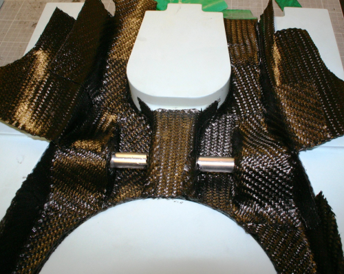
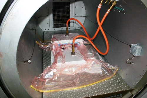
The final stage of the SMU project was to mould the two separate swingarm sections. The cut flat patterns for the plies were laid up on the epoxy moulds in the sequence specified by a ply book generated by Composites Modeler, after which the metal inserts were positioned accurately in the preform. The parts were vacuum bagged and cured under vacuum in an autoclave to minimise voids. The vacuum bagging system needed extensive development work, due to the complexity of the component geometry.
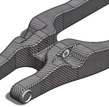
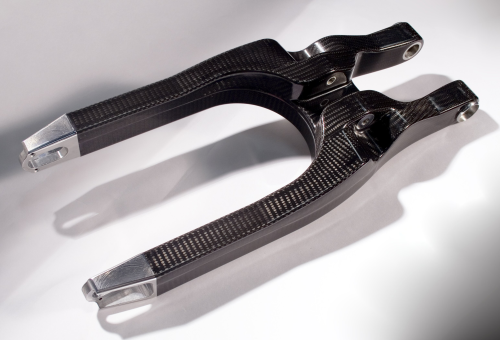
Once the two sections were fully cured, they were demoulded, cleaned and then bonded together using the 3M 9323 adhesive system. The finished, fully assembled composite swingarm was given a show room finish by first using fine waterproof sandpaper, then lacquering and polishing it to bring out the carbon fibre architecture.
Engineering students in the SMU Motorcycle Engineering Group have now fitted the redesigned swingarm onto the Honda motocross bike, which is currently undergoing on and off road trials to fully test the design.
A complete chassis?
By proving the suitability of this composite design approach in one of the most demanding areas of a motorcycle chassis, further composite design projects are now ongoing in the Motorcycle Engineering Group at SMU – the aim is to develop a complete advanced composite racing motorcycle chassis.
“Sven's work has provided us with the knowledge and confidence to proceed with similar projects,” Dr Williams states. “We now have a number of different studies underway at both undergraduate and PhD level where we are developing and characterising the modern competition motorcycle. Our ultimate aim is to produce a complete composite motorcycle chassis, with the dynamics and handling characteristics of current state of the art machines.” ♦
This article was published in the November/December 2011 issue of Reinforced Plastics magazine. To apply to receive your free copy of each issue of Reinforced Plastics please complete the subscription form.