
The new generation of aircraft designs under development makes use of materials, design, and manufacturing technologies which previously were not part of a large, commercial airframe development project. These technologies present opportunities to improve the performance of aircraft, but can also pose the risk of adding to the cost if the appropriate tools are not used and the development processes are not managed properly.
Chief among the dramatic changes in commercial aircraft design has been the heightened use of composite materials. These materials have long been used in secondary structures, but increasingly are also being used in the primary structure. The use of composite materials in the primary structure presents all the same challenges that are associated with composite piece part development, but adds the additional challenges associated with the assembly of these large composite structures that did not exist when they were primarily made out of metal.
VISTAGY provides solutions that reduce the risks and costs associated with employing these technologies through the use of an integrated approach to aerostructure development. This approach takes into account the complexity of composite design and manufacturing as well as the integration of composite components into an overall assembly.
While optimising the use of composites may present the most daunting challenge currently facing aerospace firms, managing all of the typical problems associated with developing an airframe, with its complex, highly engineered structures and hundreds of thousands of fasteners, is not far behind. Add to this the challenge of working with the extended supply chain and the need to ensure that the data can be preserved through the complete lifecycle of the aircraft, and the magnitude of the aerostructure development challenge becomes even more apparent.
Leveraging the full value of composites
To maximise the potential of composites in aircraft, engineers must be able to grasp the impact of design changes throughout the process and the supply chain and be able to make automated reuse of data; cut uncertainties and risks; and enhance optimisation by enabling faster design cycles and bypassing non-value added activities, fully leveraging the latest technologies for composite part design and manufacturing.
As the aerospace composites industry expands, competition grows more intense. Solving these design-to-manufacturing challenges is critical to maintaining competitiveness.
Conventional computer aided design (CAD), product data management (PDM) and computer aided engineering (CAE) systems alone do not address the unique complexity of composite structures. Trying to get these systems to ‘muscle’ the creation and management of the large and complex amount of data pertaining to composites engineering has proven extremely inefficient. Instead, by building a specialised environment atop CAD and CAE systems, uncertainties can be reduced both by creating and analysing the design more efficiently, and by enabling a better comprehension of design decisions across disciplines.
While three-dimensional (3D) CAD essentially helps create and manage geometry, the specialised application adds the numerous and complex composite characteristics and manages the interdependencies between these characteristics and the geometry. Therefore, the specialised environment uses the composite engineering vocabulary, helps capture design intent and trace requirements, associates characteristics to geometric features and manages relationships, enabling composite engineers to work in an environment that is well suited to their needs.
Common ground
One critical part of the composites engineering process is the interaction between design and analysis. Traditionally, these disciplines have worked somewhat separately, focusing on their own domains rather than seeing the project from a more holistic viewpoint. This arrangement made implementing changes a nightmare. It was essentially a serial process that did not help achieve the goals of quickening the pace of product cycles, cutting rework and staying on budget.
There are many barriers to encouraging better collaboration between design and analysis. Analysts think in terms of stress and strains while designers work with ply coverage, non-structural details and design rules. While the designer and the analyst almost always use different platforms, collaboration between them is enhanced when they work with shared geometry through native CAD interfaces that enables an automated response to design changes. The analyst can directly use system lines and zone partitioning to create and control a finite mesh element for a composite skin, or lines of beams or bars for stiffening elements. And he can easily communicate zone requirements back to the designer.
The assignment of physical properties is another area of common concern. The ability to easily share detailed lay-up specifications enhances the analyst’s effectiveness and significantly improves accuracy. As a result, it is possible to find higher level information that enables rapid iterations abstracted from the geometry, which leads to a simultaneous process as exemplified by the integration between VISTAGY’s FiberSIM composite software and MSC.Software’s SimXpert for analysis.
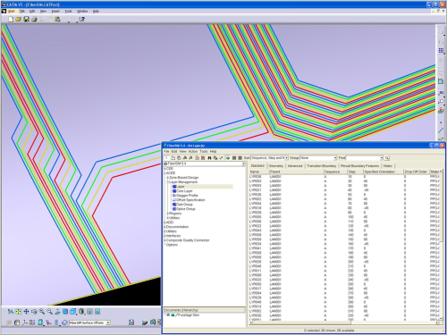
Automated composites manufacturing
Up until very recently, composite design software was largely used for parts manufactured using the hand lay-up process so all that was needed was a ply-based design methodology, a reliable draping and flattening simulation and the ability to create the manufacturing output and drawings. With manufacturing automation, the key capabilities of the composite design software are changing rapidly. Now the substance of the detailed part design, the process of moving the engineering model to the manufacturing definition of the part, must be redefined.
The objective is to determine what aspects of the manufacturing process may affect component or assembly producibility and must be integrated in the design environment. For example, a machine limitation, such as minimum course deposition, induces a design constraint which can affect ply contour and stagger layout, or interfere with a mating part footprint and modify part weight. Such constraints must therefore be made an integral part of the design parameters and cannot be left to manufacturing to deal with due to the risk of expensive iterations or over design.
VISTAGY has worked closely with the manufacturers of fibre placement machines, tape laying systems and CAM software for composites to develop a set of requirements that must be made a part of the designer’s environment in order to define and optimise composite assemblies for automated manufacturing.
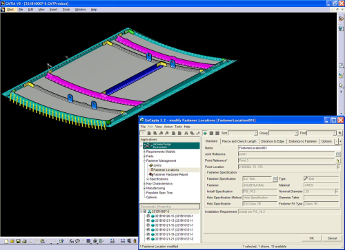
Optimising airframe assembly
It turns out that much of the difficulty in developing and managing the design of an airframe assembly is due to the need to use fasteners to secure the structure together. Even with the advent of co-cured composite structures in airframes, there are still huge numbers of fasteners which engineers must manage through successive revisions of the design. Each joint definition and its associated fasteners represent a potential failure mechanism and point of manufacturing error. Due to the evolutionary nature of an airframe design and to the sheer number of fasteners, the risk of some fasteners being out of spec and requiring rework is almost unavoidable. The same is true for the composite definition due to the mammoth amount of information necessary to define the structure.
Anything that can enable the designer to better understand the impact of change will help to account for these risks, which by definition are never fully known. Understanding changes makes the design process more efficient and adds margin to the schedule and budget of the development programme. This provides more time to optimise and verify the design, leading to a better product, on-budget and on-schedule. Any additional margin in the programme also leads to less expensive development efforts overall, improving profitability and making the product more compelling to customers.
Much like with composites, achieving this margin in the airframe assembly effort requires two important competencies. The first is managing the development of the design so that its important details are clearly exposed. In this way the impact of inevitable changes can be accounted for and addressed. The second is to assure that the design proceeds as efficiently as possible. This is not easy in an airframe design due to the massive amount of highly specialised data required to define it.
The common requirement of these two capabilities is the need to express the design in a way that exposes its most critical elements. Doing this requires an appreciation for the unique complexities of modern airframe design, i.e., large fastened assemblies containing significant amounts of advanced composites. There are literally millions of complex, interrelated details to manage in the development of a modern airframe.
The key to success is giving the design engineer solutions which enable him or her to understand the definition of the airframe design in such a way that will expose these critical elements. This approach allows engineers to work in an environment that is conducive for the type of design they are creating.
Complementing CAD and PLM systems
What’s required to accomplish this is a solution that acts as an adjunct to the current CAD and Product Lifecycle Management (PLM) design systems. This kind of solution must enable the definition, interpretation and communication of complete product and process data in a way that enables a robust change process. It should provide a powerful interface that presents the user with a system that integrates all relevant product and process information. Tight integration of the application within the 3D CAD system is essential to fully represent the design in a way that is meaningful to the design engineer.
The system stores the design data, with links to the associated geometry, directly inside the commercial 3D CAD model. It automates repetitive design tasks such as calculating ply/fastener edge distances and stack-up thicknesses, and allows for easy re-use of data for future programs. It also delivers inputs to bill of material systems and critical inspection characteristics to quality planning applications. This provides the integration necessary for enterprise resource planning (ERP) and material resource planning (MRP) systems to make the best use of the data and reduces the risks and wasted time in transferring this data manually.
Providing design and manufacturing engineers with these specialised tools makes the definition and creation of the design more efficient and accurate. However, when these tools are used as part of an integrated system for airframe development, the potential benefit is most pronounced.
Staying on top of change
A clear example of where this kind of solution is beneficial is the management of change. Change in areas such as part counts, fastener callouts, joints, assemblies, or myriad other elements of the design are ongoing for at least the first two to three years of an airframe development programme.
One of the biggest challenges for manufacturing and design engineers during this phase of a programme is to define and interpret these product and process changes in an accurate and timely fashion. Since the tools used for this work focus mostly on the definition and control of geometric data, product and process information such as specifications and callouts are not meaningfully represented. This makes the interpretation of product and process information difficult if not downright impossible.
Connecting to larger systems
What makes the development process even more challenging is that the MRP and ERP systems that are used to plan and manage the build phase of a design require this information for material and manufacturing planning. Often these systems, and the people who use them, remain starved for information, receiving only a trickle of incomplete and inaccurate information. Then just before design release these systems will receive a deluge of data. This prevents meaningful feedback on proposed changes. And because ERP and MRP systems don’t ‘talk’ with the design systems, miscommunication between these groups is effectively institutionalised due to the lack of integration of these tools.
To be truly effective, a solution should use open XML tools to publish customised sets of data to ERP and MRP systems so engineers can avoid the tedious, costly and error-prone manual entry of data into these systems. This seamless communication of data from the design tools to the manufacturing and enterprise systems is invaluable, both to those defining the data and to those consuming the data.
Another area where margin can be attained in the programme comes in the time between design release and manufacturing planning. It is at this point that the important elements of the design, such as ply definitions and fastener/hole information, need to be properly understood to develop the plan on how to build the designs. A misunderstanding of the design at this point can have dramatic and expensive consequences. If the solution provides the design information to the manufacturing engineer in way that is easily digestible, then this reduces the likelihood of errors and speeds up the process.
The supply chain
The development of this new generation of aircraft materials and development processes presents a serious challenge to the supply chain. Often times, aircraft is comprised of parts from around the world, so the distributed nature of today’s supply chain combined with the complexity of the designs requires a common language and a set of easily monitored design standards to assure that specifications are met. These additional challenges translate into a large number of potential technical and schedule risks. Managing these risks is critical to the success of these development programmes so making use of specialised tools and enhanced communication between systems is more important than ever before.
In today’s highly competitive environment, it is entirely likely that the firms that adopt these kinds of specialised tools and systems for their supply chains will assume a leadership position because they will be able to consistently deliver high quality products to market faster and at a lower cost.
Whether the suppliers are making simple metallic pieces parts, highly specialised composite structure, or complex assemblies, following a consistent process, supported by specialised engineering solutions, will help suppliers conform to the unique design methodologies, assuring that the design will be repeatable and manufacturable for the life of the aircraft programme.
Ensuring data longevity
A final area where design methodologies are important is data longevity. The expected lifecycle of a modern aircraft is over fifty years. Over this time the aircraft must be constantly maintained and repaired as well as completely overhauled every few years. This requires the aircraft data to be accessible and reusable over its life. Since CAD systems evolve and the companies that make them change, are purchased, or go out of business, the OEM must be concerned about the validity and usability of its data over a period of decades after first flight.
The solution is to represent the design in a flexible way that conveys the true definition of the design, not just the basic geometric definitions typically captured using conventional CAD and PLM. By representing the unique elements of a design as a clear, unambiguous set of design items such as composite laminates, fastened joints, and other specialised design definitions, the design may be easily repurposed into different design systems as the state of the art in engineering software evolves.
An integrated approach
There is no question that complex composite structures, highly engineered assemblies, Byzantine communication with an extended supply chain and preserving the design over the operating life of the aircraft will continue to present daunting challenges. Therefore, airframe development will persistently represent a fertile area for specialised engineering software to offer valuable solutions to unique challenges.
The key to overcoming these inherent challenges is recognising that the composite definition and assembly definition of an airframe are inextricably linked and must be considered as an integrated system. It is highly likely that the firms that adopt this approach will be best suited to meet the aforementioned challenges and will thrive because they will be the ones best able to produce the most robust aircraft on-time and on-budget.


