
Filament wound composite pressure vessels have long been seen as a lightweight solution to containing gas under pressure. Aramid fibre composite pressure vessels have been used as rocket motors, for example, as apogee motors for placing satellites into orbit. Even though aramid fibres are highly anisotropic and so are usually only used in tension, the filament winding process places the fibres on geodesic paths around the forming mandrel so that, when the vessel is pressurised, the fibres only experience tensile forces. Other types of composites, reinforced with both glass and carbon fibres, are also finding wide use in pressure vessels, some for long-term applications.
The increasing use of composites raises a difficulty however. Since the beginning of the industrial revolution there have been accidents with pressure vessels and sometimes these have been very costly indeed, both economically and in terms of lives lost. For this reason, pressure vessels are rightly subjected to rigorous and periodic safety checks to ensure their continuing reliability. The difficulty is that the testing procedures have been developed for steel pressure vessels, which fail in a very different manner from that of composites. Nevertheless, all too often composite pressure vessels are subjected to testing procedures designed for metal structures and the result is that they are closer to failure after the test than they were before.
The traditional technique used for proof testing a pressure vessel is to hydraulically over pressurise it to one-and-a-half times the maximum pressure it will experience in service. If it survives, it is deemed reliable to continue in service until the next control. This seems intuitively acceptable as a method and surely the same should apply to a composite pressure vessel. Intuition is not always reliable however and it is much better to understand the processes behind this test.
Metals fail by the propagation of a crack, which will begin to grow when the stresses at the crack tip reach a critical value that depends on the applied load, the nature of the metal, the crack length and its geometry. Proof testing accepts that nothing is perfect but has as a goal to evaluate the criticality of any defect, identified or otherwise, in the structure. Applying an overload, in a hydraulic proof test, subjects any incipient crack in the metal to stresses higher than it would experience in service and what is more, the nature of the material creates a plastic zone at the crack tip, which, at lower loads, blocks further propagation of the crack. Intuition for metal pressure vessels can therefore be justified based on the mechanisms of failure of the material.
Composites do not fail in the same way as metals and it is not at all clear that traditional proof testing techniques are applicable to them.
Carbon fibre pressure vessels
Although high performance composite pressure vessels have been made for 30 years or so, they have often been for one-off applications, such as rocket motors. Over the last few years, however, an important and growing market has developed for highly pressured vessels used for carrying pressurised natural gas (NG) as a fuel for buses, other utility vehicles and even private cars. These pressure vessels need to be in service for 20 years, or possibly longer.
It is estimated that there are of the order of 4 million vehicles running on natural gas in service today throughout the world. The number is growing so that some calculate that up to 50 million natural gas vehicles (NGVs) will be in operation by 2020. Natural gas seems to occupy a privileged position for transit buses for use in large cities and in many countries a quarter or more of all new transit bus orders are for NG. The much lower carbon dioxide and nitrogen oxide (NOx) emissions given off from NGVs when compared to traditional oil-based fuels, combined with lower costs makes the NG technology very attractive.
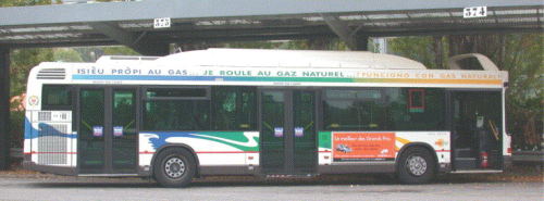
Figure 1 shows a transit bus in Nice, France, a city in which most of the buses run on NG. The pressure vessels are placed on the roof and shielded by a cover.
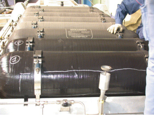
Figure 2 shows the pressure vessels with the cover removed. They are made of carbon fibres overlaying a liner of aluminium or polyethylene, which serves as the former (or mandrel) during filament winding and ensures gas tightness during operation. The choice of an advanced composite is natural as there is little interest in carrying heavy steel pressure vessels and in addition the centre of gravity of the vehicle is not raised significantly and stability jeopardised by them being placed on the roof.
The natural gas is pressurised to around 200 atmospheres (20 MPa) in order to contain sufficient energy in a reasonably small volume. The pressure vessels shown are around 1.5 m long and about 0.35 m in diameter. All this, however, is likely to be foreshadowing the hydrogen economy and pressures in the case of hydrogen will have to be much higher. Pressure vessels as shown in Figure 2 would only contain the equivalent of around 7 litres of diesel if the pressure of the hydrogen were not increased. This means that hydrogen will be stored at 700 atmospheres (70 MPa), which is a very high pressure. Failure has therefore to be unthinkable and intuition is not a sufficient guide to proof testing such pressure vessels.
Failure of composites
Composites owe their mechanical properties to reinforcing fibres and if the structure is well designed, the fibres have to break if the composite structure is to fail. This is the failure process that has to be addressed in designing a proof test for composite pressure vessels. Crack growth, as in metal, does not occur in the same way in a composite.
In the vessels shown in Figure 2 there are 150 million high strength carbon fibres in the walls, each with a diameter of 7 μm, one-tenth the diameter of a human hair. However, as has been mentioned above, the fibres experience only tensile forces when the vessels are pressurised and this suggests a way of evaluating damage accumulation in the pressure vessel. Locally, at an elementary level, the composite can be considered analogous to a unidirectional composite consisting of carbon fibres aligned in one direction. Carbon fibres show a wide range of strengths if tested individually so that on loading a unidirectional composite in the fibre direction some fibres will inevitably fail.
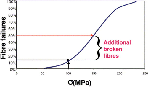
Figure 3 shows a schematic description of how fibre failures accumulate as the stress is increased. It is inevitable that a lot more fibres will be broken and the composite will only be further damaged, if the stress applied during in a proof test, is one and half times the maximum stress in service. Applying the norms for a metal pressure vessel is therefore invalid. Visual inspection is therefore proposed by some as an alternative means of control.
The aeronautical industry has a major concern about composite structures and it is this industry which has the most experience of advanced composite structures. The concern is that a composite structure tends to delaminate on the opposite side from the point of impact so that internal damage can be caused but it is not necessarily visible externally. A composite pressure vessel could have been dropped or struck and any induced damage may not be detectable by a visual inspection. Both techniques of hydraulic testing and visual inspection are therefore seen to be invalid. The only approach to determining long-term behaviour has to be based on an understanding of the microscopic failure processes in composites.
Carbon fibres are perfectly elastic so that many treatises on the subject of long-term behaviour of unidirectional carbon fibre composites assume that the composite does not change with time when loaded in the direction of the fibres. However, it takes only a transducer that can pick up the vibrations from breaking fibres and placed on a unidirectional carbon fibre composite under steady load, to show that damage continues to evolve under these conditions.
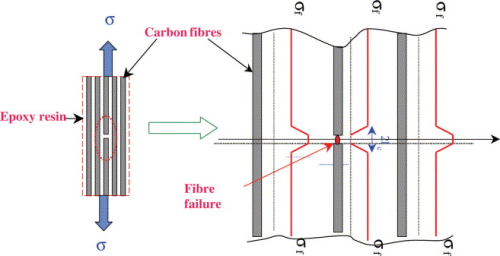
The time effects do not come from the fibres but rather from the matrix, which is viscoelastic. Short time loading provokes random fibre failures in the volume of the composite and they are isolated from one another by the shear of the matrix. Intact fibres, neighbouring each fibre break, experience, locally an increase in stress as they have to support the load that the broken fibre formally held. This is shown in Figure 4.
This means that the probability of their failure has locally increased. However over a longer time interval the probability of their failure increases as the damage zone associated with each broken fibre increases in extent. This is a sort of natural ageing of the composite when it is loaded and leads to additional fibre breaks. The rate at which damage increases is a function of the applied load and the level of accumulated damage, which translates as the density of the damage in the composite.
The increase of damage under a constant applied load can be monitored using acoustic emission equipment and is found to be very regular. This means that the curve of damage, N, as a function of time, t, can be described accurately by equation 1, in which A is a constant for a steady load, τ is a time constant and n is a power which is a material constant.
dN/dt=a/(t+ τ)n
It has been shown that behaviour can be directly attributed to the relaxation of the resin in the damage zones around fibre breaks, which results in increasing levels of stress being transferred to neighbouring intact fibres (equation 1). The debonding, which occurs around the broken fibre ends, further increases the stress concentration. With time, the damage density increases and damaged zones, which initially were isolated in the matrix, begin to overlap. When this occurs the composite is no longer stable and damage begins to accelerate. For a pressure vessel this means that it has to be withdrawn from service.
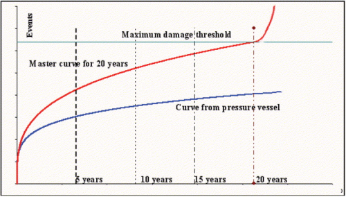
In practice it is necessary to determine the damage threshold level at which instability can be expected to begin. This involves pressurising several similar vessels to those in service to a high fraction of the burst pressure and monitoring the total number of acoustic emission events produced. Having determined the damage threshold level, it becomes possible to draw a master curve for damage accumulation at the maximum pressure experienced in service.
This master curve shows the accumulation of damage over the required lifetime of an ideal pressure vessel, which reaches its critical instability point of damage density after, for example, 20 years. The behaviour of any similar pressure vessel in service can now be compared to the master curve, as is illustrated in Figure 5.
The curves shown in Figure 5 are for pressure vessels under constant pressure but of course in service the pressure is continually varying. This is not a problem for the test as, during the control, the pressure does remain constant and as we have seen the rate of damage under these conditions is described by such a relationship. The damage rate is only a function of the pressure and damage density, no matter how the damage was created, so that it is not necessary to monitor the vessels continuously. Periodically the pressure vessels have to be pressurised to their maximum in-service pressure and the acoustic activity monitored for several hours. The number of events recorded then is compared to the number predicted for the same period by the master curve. If the number is less than that given by the master curve, the pressure vessel can stay in service. If not, it should be removed.
An advantage with the acoustic emission technique is that by using two transducers the sources of the emissions can be located. The emissions should originate randomly from all over the pressure vessel but if they are concentrated in a particular region it suggests localised damage, perhaps by an impact.
The technique answers the need for periodic in-service monitoring of composite pressure vessels and is based on a thorough understanding of the processes involved in damage accumulation in composites. It has been shown that such a test can be carried out without dismantling the pressure vessels from the bus and without disconnecting the associated gas pipes which not only reduces the down time of the bus, during which it is not in service, but also reduces to a minimum the possibility of introducing other defects in the system due to errors in reconnecting the gas pipes. The technique is therefore economic and scientifically proven.
At present, the reliability of composite pressure vessels is assured by them being largely over dimensioned, however as pressures increase, with the onset of the hydrogen economy, this cannot be acceptable. The technique should therefore remove a major obstacle to the future development of high performance composite pressure vessels and not only in the transport sector.
| Acknowledgements |
|
Professor Anthony R. Bunsell, Ecole des Mines de Paris; e-mail: anthony.bunsell@ensmp.fr Acknowledgements: The author wishes to acknowledge support that has been forthcoming for some of the above work from the Gaz de France. References S. Blassiau, A. Thionnet and A.R. Bunsell, Micromechanisms of load transfer in a unidirectional carbon fibre epoxy composite due to fibre failures. Parts 1 & 2. Composite Structures: in press. |


