
Wind turbines represent one of the most exciting segments of the fast growing market for advanced composite materials.
A June 2012 report from AMI Consulting values the global composite wind turbine blade market at an estimated €4 billion in 2011, of which approximately €1.5 billion was raw materials. AMI calculates that the global demand for materials for the production of wind turbine blades grew by over 20% per annum in the last five years.
Materials used to manufacture rotor blades for wind turbines are subject to special requirements. The number of load cycles and the load variability are far beyond what is encountered by other structures in aviation, shipbuilding and bridge building.
The development of new materials is also driven by the economics of wind turbine design. To maximise return on investment, the average blade size is growing longer and heavier requiring greater quantities of raw materials. As blade length approaches 90 m, increased sophistication in blade design, materials and manufacture are required.
A larger surface area of the blade effectively increases the tip-speed ratio of a turbine at a given wind speed, increasing the amount of energy that can be produced. An important goal of larger blade systems is to control blade weight. Since blade mass scales as the cube of the turbine radius, loading due to gravity constrains systems with larger blades.
Increasing use of carbon fibre
Manufacturing blades in the 40-50 m range involves proven fibreglass composite fabrication techniques. For larger blades – currently limited to about 73.5 m – advanced composite materials pioneered in the aerospace industry are being specified.
“Materials and manufacturing methods are evolving,” confirms Scott Hughes, Test Methods and Research and Development supervisor with the National Renewable Energy Lab (NREL) in Golden, Colorado, USA.
Carbon fibre reinforced laminates offer the greatest stiffness and strength to weight ratio. Carbon fibre reinforced load-bearing spars can reduce weight and increase stiffness. These benefits increase as blade size increase. The use of carbon fibres in 60 m turbine blades is estimated to reduce total blade mass by 38% and decrease cost by 14% compared to 100% fibreglass.
“Carbon is being used more,” says Hughes. “It is possible to make very large turbine blades from glass, but there are load advantages to lighter weight (carbon) blades.”
Carbon fibres have the added benefit of reducing the thickness of fibreglass laminate sections, further addressing the problems associated with resin wetting of thick lay-up sections. Wind turbines also benefit from the general trend of increasing use and decreasing cost of carbon fibre materials.
Tailoring of blade properties will become more important for passive load mitigating designs at very large scales, Hughes notes.
Testing and evaluation
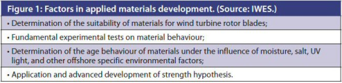
The optimisation of the design and construction of rotor blades for the new generation of wind turbines requires a wide range of mechanical, fracture-mechanical, physical and chemical properties of the materials to be known (see Figure 1).
The unique loads to which materials are exposed in the wind energy sector puts special requirements on those materials, according to research performed at the Fraunhofer Institute for Wind Energy and Energy System Technology in Bremerhaven, Germany.
Those requirements include fatigue behaviour, high resistance to wear and production related thermal and rheological properties. The determination of the specific properties of individual materials is vital.
Testing and evaluation of composite materials used in wind turbine blades can lower the cost of development of the technology and can be used to predict the performance of the composite materials, according to Kevin Cadd, technical programme manager for Gurit a manufacturer of wind turbine materials and components based in Switzerland.
“The design engineers are able to generate computer models and conduct finite element analysis in order to predict the behaviour of the materials as part of the finished structure,” Cadd says.
The analysis enables design allowables or minimum material requirements to be set in terms of specific properties.
“For example, the stiffness that a turbine blade might require to avoid hitting the tower when at full operating speed could be expressed, in very basic terms, as a minimum tensile modulus of the unidirectional laminate used in the spar component,” he says.
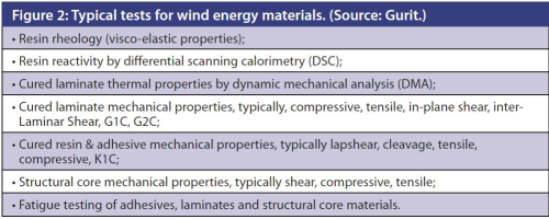
Gurit testing labs based in Canada, China and the UK are capable of conducting the majority of mechanical tests, as well as a wide range of analytical tests. The range of materials that can be tested includes uncured resins and adhesives, cured laminates and components (see Figure 2.)
Among the greatest challenges to testing materials used in high performance composites is the range of international standards, some still in development, that can be applied to the process. As the wind energy market matures, customer requirements are now tending towards aerospace or automotive standards, whereby a level of capability is required in addition to basic qualification data.
“This requires further testing and therefore investment on the part of the material manufacturer,” Cadd says.
International test standards can differ greatly depending on the requirements of the customer or certification body, the results obtained can be significantly different making comparison of systems and data particularly difficult.
“Test data is particularly sensitive to minor defects in small coupons,” reports Cadd. “Therefore, sample preparation is vitally important to achieve reliable results.”
| There are numerous mechanical and analytical equipment manufacturers, each tending to develop and supply bespoke software. Each test generally requires a specific piece of equipment. In order to have a comprehensive set-up, a great deal of investment (equipment & expertise) is required. |
Identifying the underlying customer requirements can be the most difficult aspect of any product development. Gurit uses a dedicated Composite Processing Team to understand how customers use the materials so that this can be replicated and accounted for during the test coupon manufacture.
There are numerous mechanical and analytical equipment manufacturers, each tending to develop and supply bespoke software. Each test generally requires a specific piece of equipment. In order to have a comprehensive set-up, a great deal of investment (equipment & expertise) is required.
“For example mechanical testing set-up typically has one main instrument with numerous separate mechanical testing rigs for each property and in many cases for each International Standard,” Cadd said.
The data gathered from these tests are compared against a predetermined matrix based on customer requirements. At the start of the development process a number of Critical to Customer Quality properties are identified and tests required to evaluate these requirements are specified.
Throughout the design of the material, testing is integral in the development process. Once the design is finalized, the Critical to Customer Quality parameters are translated into Quality Control measures on production material.
“These measures can range from incoming raw material inspection to finished product analytical or mechanical testing. Each Gurit facility has a separate quality control laboratory with the capability of completing all required quality control tests,” Cadd said.
Mechanical behaviour
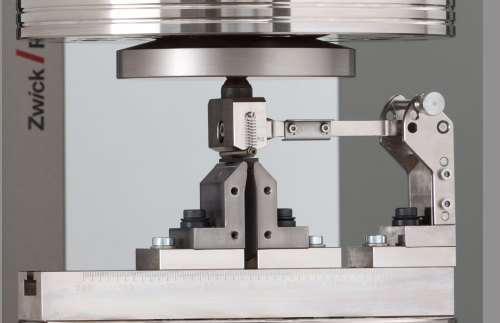
Fibre orientation and the fibre-matrix connection are among the key figures shaping the mechanical behaviour of carbon fibre reinforced materials used in wind turbine applications, according to Helmut Fahrenholz, industry manager for composites at Zwick/Roell. Based in Ulm, Germany, Zwick/Roell is a leading manufacturer of testing equipment for mechanical fibre composite characterisation.
“A large wind blade for example will be submitted to strong centrifugal charges along the blade axis,” Fahrenholz says. “A unidirectional composite can bear this main load perfectly when shaped correctly.”
Zwick has developed a line of testing equipment, software and protocols based on international standards. It offers a complete range of equipment for static and dynamic characterisation of fibre composites used in wind turbine manufacturing.
“Our most recent development is a completely modular system for static testing that integrates all test fixtures for tests on a large research scale,” Fahrenholz reports.
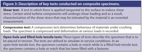
Typical tests conducted on fibre composite specimens include shear, end and end-loading compression, plain, open-hole and filled-hole tensile as well as open-hole compression. This characterises the three normal stresses in a nine component stress tensor.
The six shear stresses of this tensor can be found by specific test methods such as the ±45° in-plane shear test, the v-notch shear test, lap shear test or, for the materials qualification, the short beam shear test.
The data obtained through the testing of coupons can be used to measure/predict the performance of the composite materials in real life applications such as wind turbine blades, but quantification of as-built composites is still important, says NREL’s Hughes.
“Gaps exist between the coupon level and full-scale demonstration,” he says.
Both estimating the behaviour of the full-scale structure including representative coupons (effect of defect) is important, as well as testing at the full-scale to capture scale effects (quantify as-built blade with as-built properties), he notes.
Coupons may not capture representative behaviour at full-scale. Full-scale testing is expensive and involves protracted time scales. Effect-of-defect testing is important as challenges of scale of wind composites include characterisation of manufacturing variations, according to Hughes. ♦
This article was published in the September/October 2012 issue of Reinforced Plastics magazine © 2012 Elsevier Ltd. All rights reserved.
The digital edition of Reinforced Plastics is distributed free of charge to readers who meet our qualifying criteria. You can apply to receive your free copy by completing the registration form.


