
There is a continuing demand for tool innovations to cut, shape and drill composite material applications in almost every industry sector. Composites, each presenting a unique composition, are rapidly replacing traditional building materials - steel and aluminium in aerospace applications, as well as within marine, building supply and automotive industries.
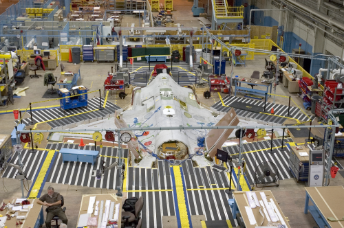
Commercial and military aircraft now incorporate a high percentage of composite, taking advantage of their utility as moulded parts and structures and their extraordinary strength to weight ratios (see Table 1). In Boeing’s next generation commercial aircraft, the 787 Dreamliner, 50% (by weight) of its primary aircraft structure will be made of composite. The exterior of Lockheed’s F-35 Strike Fighter, about to go into production, is nearly 100% composite.
As new composites are introduced (almost daily), tool makers not only respond with effective solutions but help lower machining costs and solve a variety of related production floor scheduling and management problems. As detailed in the case history below, Lockheed recently carried out a process change on its F-35 programme, acquiring custom cutting-tool geometries that helped to extend tool life-cycles that substantially lowered production costs.
Inside a composite
Inherently, no two composites are the same. Their internal texture is nothing like the uniformity of aluminium or steel, which can be expected to remain consistent from a drill’s entry point to its exit. However, no such uniformity can be expected from carbon fibre reinforced plastic (CFRP). The complex compositions of CFRP present never before encountered conditions for conventional tools and unexpected challenges for machinists that now demand custom tools designs and materials.
CFRP is commonly composed of a matrix base material, reinforced with a mix of extremely hard and strong carbon fibres. These fibre threads may be laid out either in a consistent direction, an opposed weave pattern or any combination of complexity. Thin layers of the composite sheets are stacked up to a variety of desired thicknesses and may include layers of aluminium or titanium to form composite blocks, boards and moulded shapes.
To add mass or strength, foam or honeycombed core structures may be inserted between composite layers or attached to them. Layered and moulded configurations are designed according to the specific need and specified part that may be several inches in thickness. While core layers can strengthen a composite form, composite material strength is primarily due to its ratio of strength to weight – a ratio that translates into a lighter and stronger material.
Strength to weight ratios
Carbon fibre (mostly carbon atoms), the primary CFRP strength ingredient, is extremely strong when bonded as compared by weight to aluminium or even the hardest steel. CFRP tensile strength ranges between 1500-3500 MPa (carbon fibre alone is shown in Table 1) as compared to aluminium, at between 450-600 MPa and steel, at 750-1500 MPa. As for weight or density, carbon fibre epoxy composite has been rated at a low 1.5-2.0 g/cm3, compared to aluminium at 2.76 and steel at a whopping 8.01).
Geometries – prime factor in tool selection
The purpose of a drill is to cut and remove material, producing a clean and precise hole. The hardness and geometries of the tool’s cutting edge are two critical factors when choosing the tool for your application. Of the two, point geometry is of primary importance because the geometry of its cutting edge determines the efficiency of the tool’s performance.
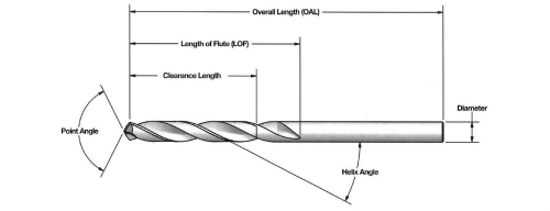
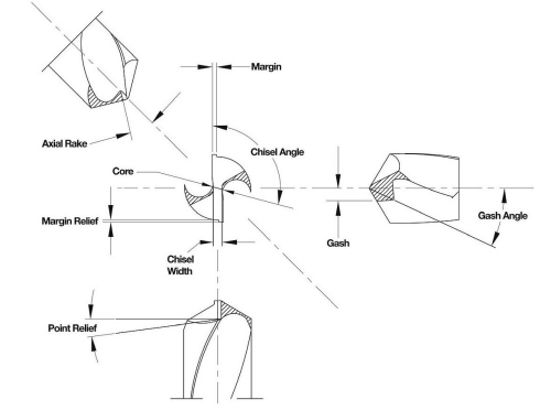
Point geometry design is a sophisticated technology with which to manage the complexities of drill point characteristics (see diagram). Master tool makers are faced with the challenge of balancing an array of precise drill characteristics such as the flute, point, gash, chisel, helix, relief, rake, land and dozens of other facets, all describing various parts of the drill.
How to achieve the best balance for a given application is far too complex a subject to cover in this space, however a quick review of general rules will help the reader gain an insight into what some call an art and others call the science of custom tool making for composites.
Example: The diagram illustrates a flute construction that provides a route for evacuating chips and particles away from the drill point. While necessary to carry debris away from the point so that the drill’s cutting surface remains in contact with the part, the flute is created by removing a large percentage of the drill’s shank, which obviously weakens the tool against breakage.
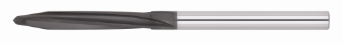
Please notice in the photo of the composite drill that four flutes have been ground, which is only possible because it is made of the very strongest tungsten carbide steel. Additionally, the drill is protected by a CVD (chemical vapour deposition) diamond coating, that protects the precise geometries and allows material to slide up the flute smoothly and quickly, thus lowering heat and stress that would otherwise contribute to breakage. This innovative flute design is capable of removing a massive amount of material, which in turn allows faster speeds and lower span time (time the drill is in contact with the part).
Keep in mind, there is no perfect drill. If there was, it would last forever. Nevertheless, working off this example and allowing for generalisations, the following axioms offer a quick tutorial on some of the outcomes of this very complex discipline:
- you can make a drill cut better, but you lose longevity;
- if you gain point longevity, you lose feed-rate;
- when you gain strength, you lose chip evacuation;
- if you gain chip evacuation, you lose rigidity (which is not the same as strength); and
- when you gain tensile strength, the tool becomes susceptible to breakage.
To summarise, when you choose one improvement to a drill, you tend to lose another advantage. And, increasing the challenge, there are literally dozens of variable characteristics to manage. That is why those who practice this art/science are called master tool makers.
| Material | Ultimate strength (MPa) | Density/weight (g/cm3) |
| Carbon fibre | 5650 | 1.75 |
| Steel high strength alloy | 760 | 7.8 |
| Aluminium alloy | 455 | 2.7 |
| *Values depend on manufacturing process and purity/composition. (Source: A.M. Howatson, P.G. Lund & J.D. Todd, Engineering Tables and Data, p.41.) |
"My experience is that most operations are using drills that are easy to order from a catalogue but are not designed specifically for the application,” says Peter Diamantis, plant manager at AMAMCO Tool. “The resulting poor performance is not the fault of tool manufacturers that market otherwise excellent tools for machining traditional aluminium and steel parts. But for composites, custom applied geometries are rapidly becoming a ‘best practice’ trend in the industry.”
Solid carbide tool options
An industry standard, the solid carbide tool continues to be the most widely used tool for machining composites and traditional steel and aluminium materials and has been in use for over 50 years. Widely and readily available, this tool can accommodate the broadest range of cutting geometries. The low commodity price of carbide allows shops to consume many units before approaching the cost of using CVD diamond coated carbide or the more costly PCD (polycrystalline diamond) technology. Additionally, the solid carbide tool can be re-sharpened many times, further extending its effective life.
CVD diamond coated tools
The CVD diamond coated carbide tool is a solid carbide tool coated by a protective diamond surface that extends up to 10 times its useful life cycle. Among the variety of coating processes, the preferred chemical vapor deposition (CVD) diamond coating was commercialised nearly 20 years ago for non-ferrous cutting tool applications. CVD diamond coating is a well-established technology for machining graphite and abrasive carbon material. CVD diamond coatings consist of 100% pure diamond crystals that are actually grown directly on carbide in a vacuum chamber using superheated filaments to activate hydrogen and methane gases. The resulting vapour mixture bonds to the surface of tungsten carbide in thickness that is controlled within a range of 3-30 microns.
Diamond coatings protect the entire cutting surface of complex geometry tools. Unlike the cobalt binder used in making PCD tools, the chemically inert properties of diamond do not react with composite resins during machining. Increasingly, with the right tool geometries and recent advances in multi-layer coatings, even extremely abrasive composite materials are being efficiently machined to exact tolerances using diamond-coated solid carbide tools. A diamond coating on a solid carbide tool preserves the tool’s edge geometry while protecting the tool’s entire surface and can extend its useful life by as much as 10 times.
PCD
Polycrystalline diamond (PVD) is a synthetic diamond application produced by ultra-high pressure and heat which is applied to a carbide tool in a diamond powder mixed with a metal matrix binder. There are basically two types of PCD tools. One uses a brazing process, inserting a PCD blank into a groove that has been cut into a carbide tool body. The other uses a sintered vein process that bonds diamond powder and binder that is inserted into a groove along the carbide body. Heat and pressure are then applied to create the PCD application and at the same time bond it to the carbide tool body.
Both PCD technologies produce diamond-hard cutting edges. However, PCD geometries are very limited and their cost is comparatively quite high due to an expensive and lengthy manufacturing process. The unit cost of a PCD tool ranges from 3 to 5 times the unit cost of a competitive CVD diamond coated carbide tool and as much as 6 to 10 times that of a non-coated carbide tool.
The Composite Drill
Lockheed Martin Aeronautics Co manufactures major components for the F-35 Joint Strike Fighter, the next generation fighter jet being developed by the US Department of Defense and eight other partner countries.
| Overall tooling cost | 97% reduction |
| Span time | 75% reduction |
| Tool life – holes per tool | 450% increase |
| Feed rate | 12 times faster |
This case study illustrates how Lockheed Martin achieved improved quality machining results in less time while significantly reducing total tool cost. An originally specifiied PCD tool was replaced by a CVD diamond coated carbide tool made by AMAMCO Tool.
Once undertaking a process change test at Lockheed revealed that precise cutting edge geometries of the CVD tool allowed operators to greatly reduce span time and increased feed rates. The resulting tool and process change netted a 450% increase in the number of holes drilled per tool.
After implementing the AMAMCO tool into the programme, test results (Table 2) showed the CVD diamond coated drill produced over 1200 holes compared to 275 produced by the PCD drill on the same task. Test results also showed a reduced span time of 75% and an increase in feed rates of 12 times faster than the original drill.
In the aggregate, Lockheed achieved a 97% reduction in tool cost. The process change savings represent very substantial cost reductions over the course of manufacturing the expected 2783 F-35s planned for production.
Tool solutions for composites
Speeds and feeds play a major role in the performance of any cutting tool, especially when working with today’s advanced composites. Keeping thrust to a minimum can reduce heat and friction created at the cutting edge, as does the CVD coating. Reduced heat and friction at the cutting edge resulted in longer tool life and a higher quality cutting edge or surface.
Solid carbide will remain the tool standard for machining composites, and both PCD and CVD diamond coating solutions are increasingly available. Tool choice will likely continue to be based on budget and job floor factors that are complex and often complicated by material availability and project schedules, beyond the control of production managers. However, tool performance and choice will increasingly be based on the two attributes determining a cutting tool’s effectiveness and efficiency - cutting edge geometry and hardness.


