
Designing a new device, engine, vehicle or best-in-class product with reinforced plastics is a complex process with only a limited amount of time for researching new materials and materials combinations, plus prototype testing and fine tuning during manufacturing to meet product release deadlines. Designers often struggle with balancing the possibility of breakthrough ideas with the time needed to test and demonstrate them.
To find ever faster routes to innovation as a competitive edge, designers are turning more and more to software tools. These are used within the computer aided engineering (CAE), computer aided design (CAD), computer aided manufacturing (CAM), computer aided three-dimensional (3D) interactive application (CATIA), finite element analysis (FEA), computational fluid dynamics (CFD) and computer numerically controlled (CNC) machine operations environments.
Multi-scale design, what-if scenarios
Simulation tools, states Thierry Marchal, Industry Marketing Director, Materials and Consumer Care, of ANSYS Inc, headquartered in Canonsburg, Pennsylvania, USA, have to answer the challenge of multi-scale phenomena.
“The key word is ‘model',” he says. “We don’t calculate the reality, we model the reality with great accuracy. In order to get quick results on a standard computer, a microscopic model can be developed to investigate the interaction between different materials. Based on this, a macroscopic model can then be developed for the whole structure of a boat or car or plane or parts of it in which composites are used. This transition between the different scales of the important phenomena is where great progress has been made, by both ANSYS Inc and many partners involved in developing analytic and simulation software for composites.”
The ability to perform multi-scale virtual prototyping reduces cost dramatically and speeds up the entire iterative process from concept to design to manufactured part. This February, ANSYS released its version 11.0 suite of CAE simulation products. Overall, enhanced functionality of the suite includes advanced meshing, optimisation, multiphysics and multibody dynamics. Among specific new features:
- more physical models of the complex non-linear behaviour of composite material components, including reaction of the composite materials as a whole, and more accurate modelling of the cohesion between parts made of different materials via advanced 'contact' modelling;
- for single parts made of composites within assemblies, seamless interfacing accomplished with existing customer CAE systems. As examples, Marchal cites the ability of ANSYS software to interface with Moldflow Structural Alliance (MSA), another supplier's 3D structural analysis for fibre filled materials, and e-Xstream's DIGIMAT microstructural analysis software (see ‘Micro world’ section).
Along with the materials multiphysics function, advanced fluids analysis (ANSYS CFX) can be combined with the ANSYS Workbench platform to link all the elements of geometric design. New solver technology to reduce time when performing transient solutions comes in the form of the Variational Technology (VT), an advanced predictor-corrector algorithm to reduce the number of iterations for non-linear static and transient analyses.
“In the CAE field, this kind of analyses usually results in long run times,” says Marchal, “and this has discouraged users from performing what-if scenarios that might provide information about how a design performs in the real world. Through VT, ANSYS has reduced the overall number of initial iterations needed for non-linear static and transient analysis by two to five times, and with VT Accelerator, can make re-solve analysis three to ten times faster for parameter changes.”
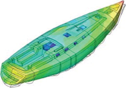
Marchal emphasises that ANSYS software products have been routinely used with other complementary tools to develop a variety of composite applications. For a low-orbiting microsatellite, ANSYS Mechanical technology modelled the materials physics for replacing metal with composites in the high temperature, compact electronics enclosure. Modelling optimisation resulted in mass savings of 29%, and the project was completed in only 18 months. Working with Componeering Inc, ANSYS software has been applied to the design of a 75-ft Wally-class racing yacht, which features a unique canting keel for balancing the moments produced by the sails.
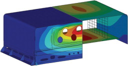
In simulation of a liquid-hauling truck with a filament wound/sandwich structure tank, the ANSYS Workbench platform transformed the CAD geometry of the tank support structure to the FEA model, using advanced contact features and automatic meshing capabilities. The tank design was optimised and validated against certification requirements. Marchal notes that “such software interactivity can indicate the weakest point in a composite structure, the weakest ply in that location, and the most likely mechanism of ply failure. This information gives users valuable insight for making informed decisions on refining the structural design.”
FiberSIM composite product development software from VISTAGY, of Waltham, Massachusetts, USA, transforms existing 3D CAD systems into a specialised engineering environment especially for composites development. In May, VISTAGY announced FiberSIM 5.3, enhancing its open and flexible end-to-end, 3D CAD-integrated architecture. Further, quality engineers will now be able to utilise 3D product design data, generated by FiberSIM and captured in a master CAD model, to automate quality planning tasks and create inspection characteristics much more efficiently.
Other specific new features:
- non-crimped fabric (NFC) materials tracking through an ordered series of orientations, reducing the time and effort to create part specifications and for manufacturing and quality planning to ensure part accuracy;
- automated generation of staggered plies with similar orientation in a set of laminates based on specifications, so hundreds of plies can be designed faster;
- generation of ply and weight tables as standard; and
- support for IBM's ElFini FEA software as yet another FEA package supported by FiberSIM's architecture.
These features add to the core of FiberSIM capabilities in delivering a crucial competitive element: faster and more efficient time-to-part. This is seen in the improved structural-based design capabilities, feedback on designs and changes shared efficiently and quickly across teams and the supply chain, and faster, more automated part specs verification so as to compress the manufacturing cycle.
FiberSIM's success in the composites market can be seen in recent purchases and partnerships:
- JETCAM (May) in a technology partnership combining FiberSIM with JETCAM's Expert CAM and nesting software to provide a seamless design and manufacturing environment from concept design to the cutting machine;
- by the GERG Group (May) of Hohenthann, Germany, to improve the engineering process for developing complex racing car parts, including for Formula One (F1) vehicles. Parts such as wings and struts are comprised of hundreds of plies and can exhibit complex curvature that cannot be easily or quickly defined by CAD software alone. With FiberSIM operating inside GERG's existing 3D CAD system, engineers can reduce delays that could affect stringent F1 delivery deadlines. The ability to share data across manufacturing and quality teams can also ensure that durability and safety specs are met;
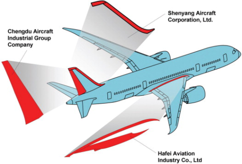
- by two subcontractors to Boeing (June) for composite B787 components – Chengdu Aircraft Industrial Group and Alenia Aeronautica. Chengdu is manufacturing the 10 m long by 3 m wide composite rudder (carbon fibre/toughened resin skins over core) on the Dreamliner, and Alenia is responsible for two tape-laid centre fuselage sections that are joined into the one piece, primary structural barrel.
The B787 has an estimated 30 tonnes of glass and carbon fibre composites per aircraft, and Toray Industries is the single prepreg supplier. FiberSIM's Advanced Composite Engineering Environment (ACEE) is Alenia's software choice for shortening design cycle times and mitigating potential manufacturing errors. ACEE can generate laminate requirements, zone transitions, ply boundaries, ply books, and variable offset surfaces, along with smart darting and splicing capabilities. Alenia's fuselage parts require use of the largest autoclave in Europe.
Both companies in their own right – Alenia as the largest Italian aerospace manufacturer and Chengdu as the leading Chinese supplier to the global aviation industry of complex and innovative composite aerostructures – are also utilising FiberSIM beyond their Boeing contributions. Chengdu Aircraft is using the software for all its composite development programmes, after achieving design cycle reductions of 60% in a project with FiberSIM applied for conceptual and detailed design, and engineering design. Other advantages cited by Yougi Wen, Director of Chengdu Aircraft's Composites Department, include FiberSIM's ability to simulate fibre placement, tape laying, and resin transfer moulding (RTM) processes.
VISTAGYs view on composites in the aerospace market – currently estimated at more than US$7 billion, with the production of finished carbon-fibre composite components and structures accounting for $5.5 billion – comes from Steve Luby, president and CEO.
“In the coming years, aerospace engineers will need to completely re-engineer their entire product development process to realize the business benefits and technology advancements that composite materials promise,” he says. “Their success depends upon how well they transform their engineering processes and streamline their global supply chain.”
Steering toward growth
The first composite tail fin for the B787 was completed in March of this year by Boeing's Composites Manufacturing Center in Frederickson, Washington, USA.
“It's the rudder that will carry the programme into the future,” stated Stephen Westby, Vice President of Manufacturing for Boeing's B787 programme, at that time.
The entire tail fin structure is 2500 lbs (1130 kg) and 33 ft (10 m) long, with the rudder made by Chengdu attaching at the rear of the structure. More than 14 000 miles (23 000 km) of composite tape was used in the B777 tail sections, an aircraft with 30% less composites by weight than the B787.
A key to more efficient manufacturing and assembly of the B787 tail section, which uses significantly less hand drilling and smaller tooling overall, is the OEM's application of ESI Group's composites simulation and virtual prototyping software (including SYSPLY, PAM-RTM, PAM-CRASH 2G and PAM-QUIKFORM). Simulating the rudder's cure process in the autoclave as well as in operating conditions gives Chengdu the chance to identify any potential materials or manufacturing defects to avoid such difficulty in the time-to-part of the finished rudder components.
Engineers at ESI ATE, a subsidiary of ESI Group in China, have been working with Chengdu Aircraft over the past six months to implement the software technologies utilised in manufacture of the composite rudder project. Chengdu's Wen calls ESI's virtual simulation software 'revolutionary,' in the sense of changing the company's entire thinking and process for composite design and manufacturing.
“It enables us to know well in advance, as early as preliminary design, what kind of defects might occur in the composite parts based on the different manufacturing methods and the design requirement of the aircraft's performance,” he explains.
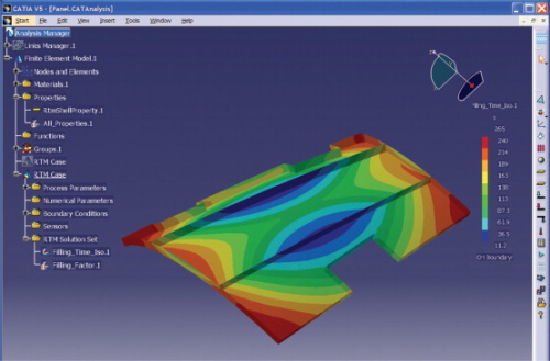
In June, ESI announced the release of its physics-based PAM-RTM for CATIA V5, which makes modelling of thicker composite parts and thermal management within liquid composite moulding processes such as RTM, vacuum-assisted RTM (VARTM), and vacuum-assisted resin infusion (VARI) easier to optimise. PAM-RTM interfaced with CATIA V5 is especially suited for designing and developing new tooling for these thicker, larger parts by linking mould design and simulation results with no loss of information due to geometry conversion and transfer.
Vincent Chaillou, President and COO of the ESI Group, points out that PAM-QUIKFORM compatible with CATIA V5 enables the simulation of unidirectional composite deformation during the draping process.
“This engineering environment includes design options like flattening and 2D/3D transfer, with exportable data to digital manufacturing machines such as automatic laser pointer or nesting and cutting programs available in Dassault's Component Application Architecture (CAA) V5,” he says.
Automotive composite parts such as hood, trunk panels, bumpers and chassis are also utilising PAM-RTM, with the advantage that the CNC-controller of the RTM machinery can be part of the simulation process.“This allows for adjustments in real time,” Chaillou explains.
Whatever the end use application, he indicates that customers are seeing the maximum value of simulation software for reducing time-to-part when it is implemented at conceptual design phase and throughout the development process, rather than when manufacturing problems occur.
Another of ESI Group's new software products is VisualDSS, an open, multi-domain environment compatible with customers’ best practices that enables building and managing multi-domain simulation models, automating processes and workflow, managing simulation content and data, and providing knowledge-based decision support and automated reporting. Chaillou expects a company announcement by year's end regarding use of VisualDSS “with our first customer within a total composite design and manufacturing chain.”
Micro-world
Modelling materials behaviour is at the heart of the multi-scale look an OEM can take with computer simulation of a composite product: from the microstructure of the beginning composite material to the microstructure of the manufacturing process-induced material in the final part. DIGIMAT 2.2 software from e-Xstream engineering, of Louvain-la-Neuve, Belgium, offers just this perspective. DIGIMAT can interface with Moldflow injection moulding software, as well as advanced non-linear FEA systems from ABAQUS (Standard and Explicit,) ANSYS Inc and LS-DYNA.
“We predict composite behaviour from the measure of each phase of the material, considered separately,” Dr Roger Assaker, CEO, explains. “For example, microstructure morphology described by the reinforcement content (such as fibre volume or weight fraction), shape (such as length/diameter), and orientation (based on how the fibre is oriented and distributed during processing), fibre orientation, content and length change across the surface and thickness of the part, which influences the local material response. So what DIGIMAT does is actually model the material in-situ or in place within a composite part.”
He reports that e-Xstream has also developed eXmap software that enables mapping of fibre orientation from injection moulding mesh to structural FEA mesh. He says that among the materials modelled with DIGIMAT are short glass fibre reinforced thermoplastics (in automotive and electronic applications), long glass fibre reinforced thermoplastics (primarily for automotive), glass beads reinforcing thermoplastics and thermosets, carbon fibre reinforced thermoplastics (mainly for jet engines), and chopped and continuous carbon fibre in epoxy or cyanate ester resins (aerospace applications).
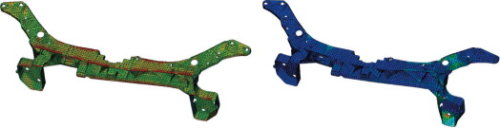
Modelling the stiffness and modal material responses of the front end carrier on a passenger automobile made with polypropylene/long glass fibre (at 40% volume fraction) required a level of simulation not provided by classical homogeneous isotropic modelling systems. The carrier structure as part of the front end vehicle module serves as the attachment fixture for the lights, fan and radiator, and the hood's locking system. Using the simulation accuracy provided by DIGIMAT, the OEM was able to observe both local and whole-part materials behaviour, including material stresses within the matrix and fibre levels.
New areas of focus for DIGIMAT materials modelling encompass nanocomposites (such as polymer resins reinforced with barite, carbon nanotubes, and calcium carbonate particles). The company has also been working for three years on development of advanced prediction capabilities for damage and failure in rate-dependent (viscoelastoplastic) plastic parts subject to crash conditions.
Personal super-computing
ABAQUS FEA software, a SIMULIA brand product from Dassault Systèmes (DS), is well known in the composites world, especially in aircraft and automotive applications. In 2004, an ABAQUS add-on, Virtual Crack Closure Technique (VCCT) became available commercially to provide fracture and failure prediction in laminated composites. Boeing originally developed the software that has since been refined for commercial application.
More recently, Airbus selected ABAQUS to perform static non-linear FEA, and applied it for advanced virtual structural testing on the A380 aircraft. This May, Version 6.7 was introduced, with a new linear dynamics architecture, CAD associative interfaces, and improved fidelity to physical behaviour in the overall non-linear materials modelling and simulation capabilities.
Dale Berry, Director of Technical Marketing for SIMULIA, explains that this fidelity “enables users to model not only the stiffness and stress in the composite structure, but also the structure's strength, damage characteristics and resistance to damage, and failure and post-failure characteristics. These higher fidelity results allow designers to improve their designs based on more accurate knowledge of the way in which their composite structures behave, and how they may be progressively damaged.”
SIMULIA initiated a Partner Program in 2006, with LMS International as the first company to join. The purpose of the programme is to unite simulation partners using ABAQUS to the DS CAA V5 community. LMS is known for its Virtual Lab product suite, including CAE/simulation of structural dynamics, noise and vibration, acoustic radiation, multibody motion, and fatigue and reliability. Reinforced Plastics asked Berry what the SIMULIA Partner Program and ABAQUS technology were contributing to a paradigm shift in the digital development revolution for composites applications.
“Several factors are enabling a paradigm shift,” he responds. “One is high-performance computing: computing speed is up and costs are down, making ‘personal super-computing’ widely available. Engineering software such as ABAQUS Version 6.7 is providing specific performance enhancements to take advantage of distributed memory parallel computers. Third, the underlying computational mathematics and software usability have made significant progress for many types of simulation, including those for laminated composite ply-based modelling, links to draping capabilities and special post-processing features to enable easier evaluation of detailed results over each composite layer. Finally, the DS partnerships are enabling integration of these simulation capabilities within a common design and analysis environment.”
Trillion dollar markets
To develop the B787, Boeing estimated 800 000 hours of time would be spent on Cray super-computers, in addition to the time on multiple software systems used by contractors and subcontractors. By 2026, Boeing forecasts a US$2.8 trillion market for 28 600 new commercial passenger and freighter planes, many of which will utilise greater composites content, and need computer software tools to analyse the materials, design and manufacture of those components.
Whether it's spacecraft, aircraft, ships, trains, automobiles or other ground vehicles built from composites, computer simulation-driven product development has become more prevalent.
“There is tremendous need for companies in all industries to shorten time to market, lower costs, improve performance and develop steady streams of knock-out, innovative products,” ANSYS Inc's Marchal concludes. “With survival on the line in many cases, OEMs use simulation as a proven way of addressing these issues.”


