
Carbon fibre is a material that has, and will continue to revolutionise the products we use every day by making them stronger, lighter and more durable. Experts estimate that the material is twice as stiff as steel and five times stronger, per unit of weight. It is made from organic polymers which consist of long strings of molecules held together by carbon atoms.
As the demand for carbon fibre expanded, the manufacturing of carbon fibre has become heavily regulated by the environmental community.
Gases, liquids and other materials used in the manufacturing process create specific strengths, qualities and grades of carbon fibre. A series of ovens and furnaces also give strands their desired characteristics by varying temperatures, dwell time and oxygen levels. The manufacturing process for carbon fibre is typically unique to each supplier, and it can be as complex as the fibre molecules themselves.
Equally as challenging as the manufacturing process are the air pollution control systems used on the production equipment. When the industry first began, the cost of operation for the first carbon fibre conversion plants were not critical design parameters and neither were the environmental effects. As the demand for carbon fibre expanded, the manufacturing of carbon fibre has become heavily regulated by the environmental community.
Emissions during carbon fibre production
Manufacturing carbon fibre can have serious environmental ramifications and pose immediate danger to humans if careful consideration is not given to emission control at the production phase of these materials.
The oxidation and carbonisation furnaces and industrial ovens have the potential to emit hydrogen cyanide (HCN) and ammonia (NH3), which are immediately dangerous to human health in small quantities.
Carbon monoxide (CO), carbon dioxide (CO2),nitrogen oxide (NOx) and volatile organic compounds (VOCs) are other pollutants of concern for carbon fibre producers, not only for their harmful effects on our environment but also their direct correlation to energy consumption at each plant.
Tar residues and silicone from the manufacturing process further complicate the destruction devices used on these applications.
As expected, the energy demand and heat input needed for the processing of carbon fibres is extensive. Producers have been met with the challenge to increase efficiency while reducing energy demands of the oxidation ovens and carbonisation furnaces.
As is the case with many industrial manufacturing operations, emissions are best destroyed through the use of thermal oxidation technologies via high temperature combustion:
CnH2m + (n + m/2) O2 ⇒ nCO2 + mH2O + heat
However very few industries use custom designed solutions like the carbon fibre processing industry does. The following demonstrates how two standard abatement technologies have been uniquely designed to meet the compliance hurdles and energy demands of carbon fibre processors.
Regenerative thermal oxidiser (RTO)
The energy efficient operation and high destruction efficiency of the RTO make it a great emission control device for a wide variety of industrial processes. However, unique aspects of carbon fibre processing dictate several oxidiser modifications in order to maintain system effectiveness, reliability and safety.
Theoretically, emissions from the low and high temperature furnaces as well as the ovens can both be handled by the RTO; however it is used most frequently for the oven exhaust.
The regenerative component to the RTO makes it ideal for handling high flow, low concentration streams. With achievable thermal efficiencies over 97% the RTO is capable of operating with little to no supplemental fuel use.
On most applications, airflow is typically pushed through an RTO in a forced draft configuration. This reduces main system fan size and the electrical consumption required for it to push process air into the oxidiser. Due to the HCN found in carbon fibre processing, many RTOs on this application are supplied in an induced draft configuration. The main system fan must be oversized to pull air through the oxidiser but it will ensure that all HCN emissions are drawn into the oxidiser for destruction, protecting the company’s employees and neighbourhood from a potentially lethal situation.
Whenever oxidising siloxane vapours in an RTO, considerations must be made to minimise the impact of silica dust build up in the heat recovery beds. The formation of the inorganic silica particulate starts at elevated temperatures and tends to accumulate within the media beds.
Heat recovery beds should be designed to prevent silica dust from collecting and clogging in the oxidiser without compromising the high thermal efficiency. If build-up does occur, the RTO media should accommodate periodic cleaning and potential replacement.
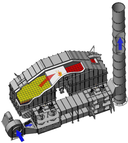
Multi-stage direct-fired thermal oxidiser (MS-DFTO)
Low and high temperature (LT/HT) furnaces on carbon fibre processes generate emission streams heavily concentrated with pollutants. This makes it an ideal application for the DFTO, however this abatement technology may require a significant amount of supplemental fuel to achieve destruction temperatures. Subsequently, they can be a large source of CO2 and NOx, which are greenhouse gases (GHGs) and contribute to global warming.
However GHGs are not necessarily a by-product of these air pollution control devices. In recent years the technology has evolved, incorporating multiple zones or stages that that minimise the effects of combustion. The MS-DFTO is being uniquely applied in the carbon fibre industry to ensure the production of these materials is environmentally sound.
During operation, furnace exhaust is pulled through the system with an induced draft fan configuration. Doing this increases safety by ensuring that all of the HC emissions are drawn into the oxidiser for destruction, protecting the company's employees and neighbourhood from the potentially lethal gas leaking out of flanges, instruments, etc. This also ensures that oxygen does not migrate back to the furnaces.
The furnace (LT and HT) exhausts are injected into the first stage of the DFTO where there is insufficient oxygen for complete combustion of the hydrocarbons. In this reducing environment, the nitrogen bearing hydrocarbons are destroyed with minimal NOx formation.
The remaining gases are quenched before moving into the next stages where total emission destruction efficiencies of over 99% are achieved. Proper oxygen control and residence time ensures high destruction efficiencies.
A selective non-catalytic reduction (SNCR) system could also be incorporated following the MS-DFTO to provide a further reduction in the outlet NOx.
Process integration
| Optimising energy recovery from thermal oxidisers will improve overall plant efficiency ... |
Today’s processors are utilising new techniques while taking a much more holistic approach when designing and optimising their plants; from polymerisation and spinning to oxidation, carbonidation, surface treatment and pollution control. Physical connection techniques as well as operational interface between the process equipment and abatement devices are critical to a successful installation. Optimising energy recovery from thermal oxidisers will improve overall plant efficiency by integrating the process heating equipment.
This year, two institutions in particular have rolled out new processing techniques that utilise different, yet highly effective air pollution abatement technologies that also drive down production costs by ultimately increasing efficiency and reducing energy demands.
Carbon fibre recycling in the UK
The strength, durability and lightweight characteristics of carbon fibre make it perfect for many manufactured products like airplanes and automobiles. However, most waste ends up in landfills where those same attributes do not allow the carbon fibre to break down like other organic material. The University of Nottingham in the UK has opened a new, state of-the-art facility dedicated to the reuse of this valuable resource.
In conjunction with industry partners, the University of Nottingham has developed a pilot scale carbon fibre recycling plant. The team set out to develop and commercialise recycled fibre that retains the material strength at a cost savings to manufacturers using carbon fibre in their products.
The team at Nottingham knew that an air pollution control device would be necessary to meet the local air emission requirements. They also realised that there was the potential to reuse some of the energy released during the combustion of these carbon fibre processing emissions.
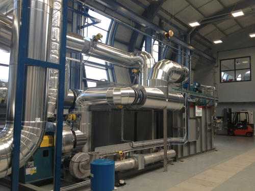
Anguil was selected to provide the air pollution control system for the University. Its experience with similar applications and ability to make a custom designed system to meet the unique needs of this pilot-scale recycling facility were the primary determining factors.
Anguil manufactured, installed and recently brought online a thermal recuperative oxidiser with dual heat recovery. An internal heat recovery process reduces the amount of supplemental fuel required to bring the process emissions up to combustion temperatures.
Technology transfer in the US
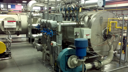
Recognising the need for this industry to develop a lower cost carbon fibre material, the US Department of Energy built a custom designed conversion process at Oak Ridge National Laboratories (ORNL). The process equipment, designed by Harper International, makes this one of the most sophisticated and capable facilities in the industry. The carbon fibre technology line in Oakridge, Tennessee, allows commercial partners to test the scalability of emerging carbon composite materials before commercial production. To treat the exhaust streams coming from the carbon fibre process, Anguil was commissioned to design, manufacture and install a MS-DFTO for off gas compliance. The abatement system is capable of destroying nitrogen compounds with minimal NOx formation which is a typical by-product in conventional oxidation processes. The gases move through the zones within the DFTO under varying conditions such that VOC emission destruction efficiencies are over 99%.
Futher information
Anguil Environmental Systems Inc is an air pollution control and energy recovery system provider headquartered in Milwaukee, Wisconsin, USA, with offices in the UK, Asia and a network of agents worldwide. The company has worked with Harper International on The Beacon, a website focused on minimising the environmental impact of carbon fibre production and driving efficiencies to yield a more profitable operation.
Since 1992, Richard Grzanka (BSME, MBA) has been involved in the technical sales, application engineering and product development of air pollution control equipment for various industrial applications. He has authored numerous technical articles on the subject of air pollution control strategies in the carbon fibre and composites industries. His current responsibilities include business development of Anguil's thermal and catalytic oxidiser systems in several target industries and international markets. ♦
This feature will be published in the March/April issue of Reinforced Plastics magazine.
The digital edition of Reinforced Plastics is distributed free of charge to readers who meet our qualifying criteria. You can apply to receive your free copy by completing this registration form.


