
A big challenge with wind turbines has always been to convert a highly variable input – the wind impinging on the rotor – into a rock-steady alternating current output suitable for grid connection.
One answer is to regulate blade pitch and power off-take so that the generator works at fixed speed in synchronism with the grid. But this can waste available wind energy, and there has been an evolution towards variable-speed drives; in such cases the generator/turbine is allowed to be driven at varying speed, in line with the wind, and power electronics are used to render the alternating current output of the generator to direct current (subsequently converting this back to ac at the required 50 Hz or 60 Hz).
This frequency conversion stage adds cost though, and introduces efficiency losses and reliability issues. In the important North American market, GE Wind Energy has a dominant position on the necessary power electronics with a variable speed patent. Wind turbine (WT) manufacturers hoping to sell into this market must either pay a licence fee or innovate their way around the patent. And innovators have indeed stepped up to the plate.
One approach is to use a type of generator that allows some variation in input drive speed and exploits an electromagnetic slip to maintain grid synchronism. The rotor current control (RCC)-type generator first developed by Weier of Germany and subsequently offered for the US market by Gamesa and Fuhrlander, is an example, as is Vestas' Opti-Slip technology. Used with active blade pitch control, these solutions can function effectively.
A no gearbox approach is to directly drive a slow-turning permanent-magnet alternator; Enercon tried to beat the GE patent with a system of this type (first pioneered by ABB), but GE challenged this because the output still has to be electronically conditioned to provide a stable 60 Hz. The result of a legal wrangle was that GE Wind Energy eventually granted a license to Enercon enabling it to market its variable speed, pitch control direct drive products in North America.
Enercon is rumoured to have had some leverage of its own thanks to a patent that could have restricted participation by US producers in the German market.
Another approach is to take out the speed variations with a variable-ratio gearbox.
Several forms of variable input speed/constant output-speed gearboxes have been tried, typically driving a synchronously rotating generator. Grid-synchronised generators rotate at a fixed speed, which is determined by the frequency of the supply they are connected to. They are self-exciting, do not need slip rings and can be grid connected without needing heavy duty power electronics.
Mechanical multi-ratio gearboxes with shifting gears are unsuitable for driving them, not least because ratios are changed in discrete steps and do not result in precise frequency matching. Fluid coupling, on the other hand, offers the possibility to provide continuous (stepless) accommodation of speed and torque differences. However, currently available hydraulic technology cannot meet the power or step-up requirements of wind turbines.
What, though, if the characteristics of mechanically geared and fluidic/hydraulic systems could somehow be combined. Could such a system meet the variable speed challenge without requiring power electronics and hence beat the GE patent
Novel approach
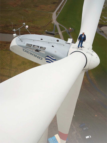
EU Energy company DeWind has set out to prove that precisely this can be done, in its innovative DeWind 8.2 machine.
This new wind turbine uses a hydrodynamic sub-system to stabilise the speed of the output shaft driving the generator, thereby avoiding the need for a frequency converter.
Relying on fluid coupling, the sub system is continuously variable, offering smooth speed regulation. Control is effected via an adjustable guide vane within the hydrodynamic (fluidic) unit. Early signs suggest that this solution, which amounts to a continuously variable gearbox, will be both effective and popular.
Vic Lilly, technical director of EU Energy Wind – which owns the DeWind company and technology – outlined the background to the development: “When we decided to produce a machine for the North American market, we looked at a range of possible solutions that avoided the need for an electronic frequency converter and a transformer at the base of the tower. The acquisition of DeWind by EU Energy at about that time gave us the opportunity to innovate. Voith Turbo in Germany had been trying to interest wind turbine manufacturers in its WinDrive, a hydrodynamic drive system, without much success. Companies professed themselves committed to their own established technologies and were not interested. But we were intrigued and went on to make our own detailed investigations.”
As a result, DeWind decided to use the technology and in late 2005 concluded an agreement with Voith to collaborate in developing the WinDrive power transmission for the 2 MW DeWind D8.2 machine. Under the agreement, EU Energy/DeWind is granted exclusive use of WinDrive for machines of up to 2.6 MW until 2013.
Achieving the step-up ratio of 1:100 needed to translate the nominal 18 rpm of the 80 m diameter rotor on DeWind's D8.2 to the 1800 rpm generator speed required to deliver 60 Hz – across the full range of rotor input power – is a tall order for a fluid-based system alone. A mechanically geared system is therefore still required, particularly for high wind speeds.
But at low wind speeds, with less power to be transferred, a hydrodynamic system could cope. Its advantage of offering continuously variable input-output speed adjustment over a wide range of torque difference would be invaluable in low wind speed situations when input torque from the rotor can vary substantially.
How, then, to combine the two types of system?
Simply switching between the systems at some set wind speed has disadvantages. Not only could the switching discontinuity be potentially destabilising, but there is a wide wind speed band over which both the geared and the fluidic elements can usefully contribute drive power, their complementary characteristics resulting in smoother, better regulated drive to the generator. It would be preferable, therefore, to incorporate a mechanism, which is able to accept power from both elements while allowing one or the other to predominate according to prevailing conditions.
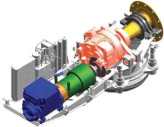
The solution the company arrived at is to combine power from the two sources in a planetary gear stage, whose output drives the synchronously rotating generator. The planetary gear's carrier is driven directly by the mechanically geared input while power from the hydrodynamic element is applied to the planetary gear itself via an annular gear. Differential rotation of the various planetary elements determines the allocation of power flows to the output shaft. Acting together, the mechanical drive and the hydrodynamic torque converter constitute a variable speed gear unit.
The fluid drive element of WinDrive is based on Voith's hydrodynamic torque conversion technology that has been in use for years in industrial and gas compressor applications.
Steady evolution has made the system highly reliable, some drives having served for decades without failure. A mean time between failures (MTBF) of some 30 years is claimed. This compares well with frequency-converting power electronics where component failures requiring service visits are all too frequent.
The fluid coupling element dampens shocks arising from wind gusts and grid faults, reducing fatigue on the drive train. This advantage translates to longer gearbox and turbine lives; alternatively, dynamically loaded components can be made lighter and cheaper for the same life.
A computer-based turbine control system with integrated SCADA and park control maintains the wind turbine at optimum operational status. Grid companies can control the system remotely. Control of the hydrodynamic element is achieved via an adjustable guide vane within the Voith unit. Servo control loops for the rotor blade angle, the guide vane position in the torque converter and the excitation in the generator are functionally integrated. A password protected remote monitoring programme permits automatic transfer of current and historical operating data.
WinDrive has shown its ability to adapt variable rotor speed to a constant generator speed commensurate with grid connection. This means that economically priced asynchronous and synchronous generators can be connected directly, obviating the need for frequency conversion. Ergo, the GE patent is not violated. In the DeWind 8.2, a four-pole brushless synchronous generator replaces the double-fed induction generator (DFIG) used in DeWind's predecessor wind turbine, the D8. Generator voltage can be 4.16 kVA to 13.8 kVA to suit different grid standards.
Simulation software specialist Dig-SILENT established by modelling the D8.2 within a wind farm environment that grid compatibility is of a high order, the system contributing to high network quality and exhibiting superior transient behaviour during grid or wind disturbances. According to a paper presented at the sixth International Workshop on Large-Scale Integration of Wind Power and Transmission Networks for Offshore Wind Farms, October 2006 in Delft, the Netherlands, the WinDrive concept offers substantial advantages for wind farm operation.
Farms based on directly-connected synchronous generators support the voltage and stabilise the system by increasing the short-circuit level. The concept can operate in islanded systems, important for applications in remote areas, remote industrial plants and small islands. Offshore wind farms equipped with such turbines can be connected to the main grid using conventional thyristor-based high voltage dc technology, advantageous when connecting large offshore wind farm clusters to shore.
EU Energy is not the only wind turbine manufacturer to utilise a variable speed wind turbine gearbox. Scanwind of Norway has tested a 3 MW research prototype with a Norwegian-designed gearbox. A Windflow system developed in New Zealand reportedly features a synchronous generator driven by a torque limiting gearbox in which a hydraulic pump is used to induce mechanical slip.
US researchers have investigated alternative gearbox concepts under the US National Renewable Energy Laboratory's WinPACT programme.
Taking the blade enhancement route
Variable speed drives enable more of the power the wind offers to be harnessed, by broadening the band of wind speed over which wind turbines can operate.
Another way to achieve this end is to enhance rotor performance through the use of larger and/or aerodynamically improved blades. In particular, this can enable turbines to operate at the world's numerous low wind sites. Up to now the main thrust has to been to equip wind turbines designed for such sites with outsize blades, but this tactic will eventually run into limits as the extra blade mass occasioned by the need to make very large structures sufficiently stiff and strong cancels out the benefits of the extra area.
The low-weight benefits of advanced composite materials, including carbon/epoxy, can extend this natural limit, but not indefinitely.
That is why research and industrial collaborators in the USA are taking the improved aerodynamics route. Dynamically superior blades are more efficient and, if engineered to spill wind in gusts, can be made larger.
Alternatively, rotors may be made lighter so that drive trains and shafts can be made ‘less massive’ than they would otherwise have to be. The Sweep Twist Adaptive Rotor (STAR) developed by Sandia National Laboratories in partnership with Knight and Carver of San Diego, is designed for use in locations having average annual wind speeds of 5.8 m/sec (at 10 m height). According to Tom Ashwill of Sandia, being able to operate at this speed would increase by 20 fold the available land area in the US where wind energy could economically be harnessed. Developed as part of the US Department of Energy's low wind speed technology initiative, STAR is intended for utility sized turbines.
The 27.1 m long glass/epoxy blades of STAR incorporate both tip sweep and blade twist. The curving swept tip helps the airflow leave the tip cleanly, with reduced drag-inducing eddies and less noise. The twist is a more dynamic feature, made possible by the aero-elastic properties of the blade's composite structure. Thanks to bend-twist coupling, the design allows the blade to twist when struck by a strong wind so that more wind is spilled from the curved trailing edge. This alleviates peak wind pressure and stress on the blades. As a result, longer blades can be specified for a given site than if aerodynamically standard blades were to be used.
These longer blades will, Tom Ashwill predicts, enable 5-10% more energy to be captured at low wind sites than with an equivalent conventional rotor:
“We've been pushing for the incorporation of innovative concepts into utility-scale blades for some time now as a way to achieve lower wind energy costs. The continued growth in average size of utility wind turbines may stop before efficiencies are maximised, unless blade weight growth (which is non-linear) can be controlled.”
Other weight-reducing concepts, including carbon spar caps, off-axis carbon fibres that facilitate bend-twist coupling, and new ‘structural’ airfoils, have been incorporated at smaller scale in a 9 m prototype blade being evaluated at Sandia's test site in Bushland, Texas.
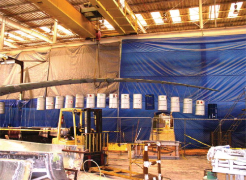
The first full-scale STAR blade is currently being tested at Knight and Carver's fabrication facility under static loading.
|
European producers have also paid close attention to blade shaping and dynamic properties.
LM Glasfiber of Denmark re-engineered the root area of its large blades so that 20% longer blades could be supported on a root of a given size than before. The LM SuperRoot concept – part of the company's FutureBlade portfolio of technologies – involved careful attention to the blade attachment area, in particular the details of the bolt holes and bolts themselves. This has benefited, for instance, the 61.5 m model.
Another FutureBlade feature is a patented system for pre-bending the blades outwards so that the rotor can survive stronger gusts before any risk of tower strikes arises.
German wind turbine manufacturer Enercon radically revised its blade design and construction to deliver an improvement of several percent in the yield of its blades. Planform improvements included ‘winglets’ at the blade tips to inhibit turbulent flow and vortex formation, a more optimum profile between tip and root, slimmer outer blade sections and a major reshaping and deepening of the blade root to improve energy capture near the turbine's sizeable nacelle.
The measured aerodynamic efficiency of the resulting E33 blade, at 56%, was within striking distance of the 59.3% figure calculated by German physicist Albert Betz as being the maximum amount of the wind's energy that a turbine could ever capture.
Enercon questioned Betz's calculations, dating from the mid-1920s, and used computational fluid dynamics to better model the conditions blades actually experience. As a result, it was able to so improve the blade aerodynamics that turbine rotational speed could be reduced by five percent even while yield was improved (also by 5%). Reducing rotational speed cut the acoustic signature by 3 dB – effectively halving the perceived noise. Reduced operating loads consequent on the improved dynamics enabled the diameter of Enercon's 30 m rotor to be increased to 33 m for the same drive train and hub. The resulting greater area swept by the rotor is said to translate into a 25% improvement in yield.
Enercon carried the same design and constructional principles through to the E70 (71 m rotor diameter) blades designed for its 2 MW turbine and the E112 (112 m rotor diameter) ‘ultra blade’ designed for 4.5 MW turbines. Tilted ‘winglet’ blade tips help account for the fact that a single E112 is said to make less noise than three smaller E66 models.