
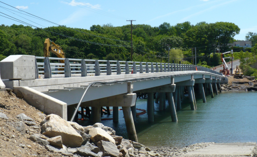
The original Knickerbocker Bridge was built in 1930 and a major superstructure rehabilitation was undertaken in 1983. It was a 38-span timber bridge approximately 535 ft in length. This two-lane highway bridge, which carries Barters Island Road over the Back River in Boothbay, is very close to the tidal waters with only 4 ft of clearance at high tide. It was key that the replacement bridge be constructed to better withstand the harsh marine environment.
HCB technology
The solution came in the form of hybrid-composite beams (HCBs) manufactured by Harbor Technologies in Brunswick, Maine.
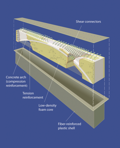
The HCB technology was developed by HC Bridge Company LLC. An HCB is structural member akin to a prestressed concrete or steel beam. An FRP outer shell provides shear strength and encapsulates the tension and compression elements. The compression element is a concrete arch. The tension element is steel reinforcement that runs longitudinally the length of the beam and ties the two ends of the concrete arch together.
HC Bridge Company describes the HCB as essentially a tied arch in a fibreglass box where 90% of the strength is provided by steel and concrete. The encapsulating FRP shell protects the steel and concrete from the elements ensuring an extended service life and minimal maintenance.
John Hillman, President of HC Bridge Company, reports that HCB is a cost-effective alternative for major infrastructure projects, providing sustainable structures that are lower in weight, safer and longer lasting than conventional bridges. The hybrid-composite beams have also been used on bridges in New Jersey and Illinois, as well as in a railroad bridge.
Knickerbocker Bridge design
A preliminary design report for the Knickerbocker Bridge recommended replacing the existing bridge with adjacent precast box beams. This recommendation was later changed to HCB after the Maine Department of Transportation (MaineDOT) researched and tested the HCB technology at the University of Maine.
The construction documents were prepared by Calderwood Engineering of Richmond, Maine, with assistance on the HCB design from Teng & Associates Inc, Chicago, Illinois.
Eric T. Calderwood, chief engineer at Calderwood Engineering, notes that corrosion and long-term durability were key factors in the design since the bridge is over the salt water and at times the water is very close to the bottom of the bridge. These factors made the HCB an attractive solution.
“We have a good history of the use of composites in a marine environment here in Maine as there are boat yards all along the coast today that use composites so it is a material that we have confidence in for this kind of exposure condition,” Calderwood says. “Further, HCB was attractive because the weight of the beams during erection would give them a considerable advantage over precast.”
In order to comply with the hydraulic criteria for the new bridge, the HCBs were designed to match the recommended 33-inch depth box beams in order to maintain the required vertical under-clearance. Also similar to the proposed precast box-beam bridge, the HCB framing system was limited to two 60 ft end spans and six 70 ft interior spans, resulting in an eight-span bridge with a total length of 540 ft.
The HCB design was tested at the University of Maine.
“One of my considerations when using something new is how it will function,”explains Calderwood. “In this case, we had a full size beam made up at the University of Maine’s Advanced Structures and Composites Center (AEWC) with arch filled and deck cast on it as it would be in the field. This beam was then fully instrumented and tested for fatigue considerations, and then once fatigue was fully satisfied it was tested to destruction. The beam had approximately four times the capacity required.”
Bridge construction
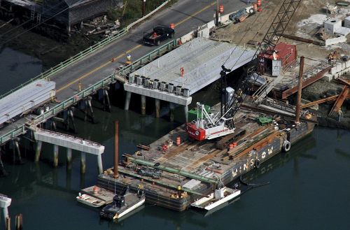
Bridge construction began in the spring of 2010 with the installation of seven pile bents comprised of concrete-filled pipe piles with rock anchors tensioned into bedrock. In the fall of 2010, prior to completing the substructure construction, the general contractor, Wyman & Simpson, began erection of the HCB units. Using HCB, the contractor was able to drive the trucks with the beams on the existing bridge and off-load them using the same barge and crane needed for the substructure. The contractor was also able to ship the HCBs across the existing timber bridge even with the posted load restrictions.
In general, the HCBs were erected at a rate of approximately eight beams per day. After setting the first four spans of the bridge, the contractor placed the concrete for the arches in the HCB units. By simply placing a hopper with a steel tube into the tops of the beams, it was possible to fill each beam in approximately 20 minutes. Again, the contractor was able to place all of the concrete compression reinforcement in one span within one day. The reduced shipping and installation costs associated with the composite structure made the solution cost-competitive with the conventional precast box-beams on a first cost basis.
“One of the biggest advantages of HCB is the extreme lightweight for shipping and erection,” says Kim Suhr, vice president, Wyman & Simpson. “Each of the 70 ft long beams for the Knickerbocker Bridge weighed only 5000 lbs. As a result, four HCBs could be shipped on a single truck instead of one truck per beam as would have been required for precast concrete beams."
"Further, we were able to erect the beams using a small crane instead of mobilising a 200 ton crane. This resulted in a significant cost savings. Further, no deck forms were required.”
Once the beams were filled, the contractor began placing reinforcing for the deck pour. With top flange widths of 4 ft, the beams were placed tip to tip so that no deck forming was required. Scupper details, screed rails and reinforcing details were no different than those for a comparable precast concrete bridge.
The first half of the deck was cast in October of 2010. After working through the winter to complete the remaining piers, the contractor completed installation of the second half of the HCB superstructure in April of 2011. The bridge was officially opened to traffic on 11 June 2011.
“What makes the Knickerbocker Bridge unique is not only the HCB framing system, but the fact that this will be the longest composite vehicular bridge in the world, the first to be made continuous for live load, and the fact that this has been accomplished with a structure that was no more expensive than a conventional concrete box beam bridge,” says Hillman.
Suhr also noted the long term benefit of HCB – its anti-corrosive properties.
“I am confident that this bridge will have a longer life span in this corrosive salt water environment than if it was constructed of simply steel or concrete,” he said. “We definitely will use HCB again.”
Other projects
Nate Benoit, P.E., project manager, MaineDOT Bridge Program, concurred, noting that they are already quoting some other projects using HCB.
“We believe HCB is a viable technology and is another tool in the toolbox for bridge designers,” he says. “HCB has proven to be a successful technology as demonstrated by the Knickerbocker Bridge Project. HCB offers corrosion resistance, is light-weight and it can be used with an accelerated construction schedule. We expect to see more of the technology used for bridge infrastructure projects.”
The project has attracted a lot of attention, including the Technology Implementation Group (TIG) of the American Association of State Highway and Transportation Officials (AASHTO). The purpose of the TIG is to identify and champion the implementation or deployment of proven technologies, products or processes that are likely to yield significant economic or qualitative benefits to the users. In June, the AASHTO TIG met in Bangor, Maine, to develop a promotional campaign highlighting various Department of Transportations that have already deployed the technology in order to educate their peers as to the benefits of the technology. ♦
This article was published in the July/August issue of Reinforced Plastics magazine. To apply to receive your free copy of each issue of Reinforced Plastics magazine please complete the subscription form.


