

An inspiring opening talk described some of the advantages provided by fibre reinforced plastic (FRP) in civil engineering and demonstrated how these have been embraced in other industries such as marine, automotive and aerospace to very good effect. Claudio Trentin from Fibres Ltd described how these experiences in other industry sectors have built up high levels of confidence in the materials and supply chain, which is perhaps lacking within the construction industry. This was identified as one of the barriers that the composites industry needs to overcome in order to expand the uptake of composites in applications such as bridges.
An architect's perspective
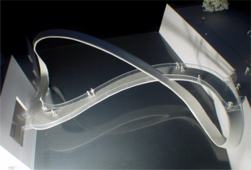
Hakes Associates is recognised as one of the leading young architectural practices in the UK, with a speciality in footbridge design. Julian Hakes explained that the bridges they have designed have been mainly steel structures and the aesthetic possibilities have been restricted by the limitations of steel fabrication. Hakes explained that they would like future structures to be more sculptural taking inspiration from nature, including plant and animal forms. He showed several dramatic designs such as the Mobius Bridge (Figure 1), which is to be built in Bristol, UK, as a steel structure.
This is clearly going to be a complex structure to fabricate in steel and will require significant ongoing maintenance, but it could be moulded in FRP to produce a much more durable solution. The composites industry clearly needs to break down the barriers that prevent FRP being considered for such projects, including cost certainty and confidence in the supply chain.
An end-user's perspective
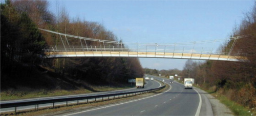
Ben Sadka is a Technical Advisor at the UK Highways Agency, which manages thousands of bridges within the trunk road and motorway network in England. He showed how FRP has become the material of choice for certain strengthening schemes to improve the capacity of existing bridges made from steel or concrete. Sadka also showed details of the Halgavor footbridge, which is a suspension bridge over the A30 with a moulded FRP deck (Figure 2).
For FRP to be adopted for the construction of new footbridges he explained that it will be necessary for FRP to be competitive with conventional materials in terms of whole life costs, including factors such as installation, traffic management and maintenance through the life of the structures. As bridges in the UK are normally designed for a 120 year life, the superior durability of FRP will provide significant advantages.
Sadka also highlighted the advantages of weight reduction and the ability to span greater distances to avoid extra supports, for example in the central reservation of major roads. But he also warned that the lightweight nature of FRP footbridges can make them more prone to vehicle buffeting and vibration – a topic that was discussed in more detail later in the day.
Opportunities and design issues
To highlight some specific design issues and opportunities John Shave from Parsons Brinckerhoff (PB) discussed a study they had undertaken in behalf of Network Rail to investigate potential applications of FRP in rail infrastructure. One of the primary findings was that there is an opportunity to use FRP in footbridge construction.
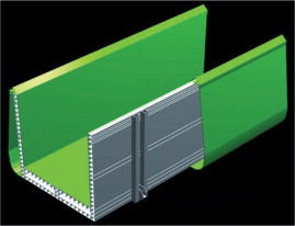
PB is currently designing an FRP footbridge to replace a corroded wrought iron bridge. The bridge is to be constructed using standard pultruded panels, enclosed with moulded aesthetic FRP panels, as shown in Figure 3. One of the primary design drivers has been the dynamic response to train aerodynamic buffeting, which has the potential to induce uncomfortable accelerations into the bridge structure as a result of the very low mass of the FRP structure.
Shave also presented some results from monitoring carried out on a lightweight bridge to measure accelerations resulting from train buffeting. These measurements were used to predict train buffeting loads that could be used for the design of future lightweight bridges. This is an important area that clearly needs further data and it is hoped that the FRP bridges currently being constructed will be monitored with pressure sensors and accelerometers to provide such data for future bridges.
Rail applications
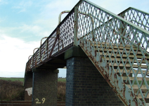
Opportunities in rail infrastructure were also discussed by Nick Speight from Mouchel Parkman, who explained that interest in the use of FRP for footbridges was increasing mainly due to the speed of installation and minimal future maintenance. There is a big opportunity to replace numerous rusty steel and wrought iron footbridges, such as that shown in Figure 4, with new FRP bridges.
Speight also explained how the reduction in mass can be particularly useful when upgrading existing structures by reducing the dead load on substructures and enabling increased live loading. The discussion highlighted several areas where there is some lack of knowledge on how to best specify and procure FRP structures and it is considered that this needs to be resolved to allow the more widespread use of FRP in rail infrastructure.
FRP decks
Wendel Sebastian presented details of tests that have been conducted at the University of Bristol on FRP cellular bridge decks bonded to pre-stressed and reinforced concrete main girders. The potentially difficult tasks of bonding FRP decks to each other and to the main bridge girders was discussed including the resulting level of composite action between deck and main girders.
The test of time
Many of the previous discussions may have given the impression that the use of FRP for footbridge construction was relatively new, but 10 years ago SP Technologies was contracted by Ideias de Futuro SA of Portugal to undertake the structural engineering of an all composite footbridge. The design, manufacture and in-service performance of these bridges was explained by Thomas Royle and Dr Mark Hobbs of Gurit (UK) Ltd (formerly SP Systems).
Three of these bridges were installed in January 1998 having taken just four months to build and 2 hours each to mount onto their pre-installed pedestals. They are constructed entirely from a high-performance epoxy resin, reinforced with a combination of woven and unidirectional glass and carbon fibre materials, using hand lay-up moulding and vacuum consolidation. Each bridge was lifted into position during a 30 minute road closure (see Figure 5).
Each bridge has a single 30 m span, with a covered walkway and open elevations. They were designed to satisfy local and national regulations including earthquake loads and a deck loading of 4 kN/m2 resulting in a total characteristic pedestrian load of 24 tonnes. The first mode of vibration was to be above 5 Hz to avoid pedestrian induced vibration. SP used in-house software and finite element analysis during the design process to produce some efficient structures each weighing only 6 tonnes, with a maximum deflection of 58 mm under the full serviceability load.
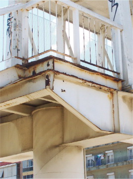
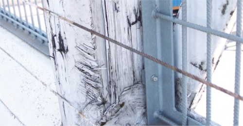
It was reported that the total installed cost was similar to that for a steel bridge. They have been on site for nearly 10 years with virtually zero maintenance, which is clearly evident by the corrosion existing on the steel supporting structures, as seen in Figure 6. It is clear that if structures are not likely to be adequately inspected and maintained then FRP offers significant advantages over steel. One of the bridges suffered from a small fire on the main deck, which has been painted over without any major repair work to the FRP structure, as shown in Figure 7. Despite the fact that they were not manufactured from fire retardant resins they appear to have offered good resistance to such vandalism and attack and are clearly much more durable than the steel supporting structure.
Haughton Road footbridge
A proposed cycle route along Haughton Road in Darlington is part of a strategic cycle network providing a safe continuous route from the north-east of Darlington into the town centre. A new foot and cycle bridge is required over the East Coast Main Line railway to provide a safe route, as the existing road bridge is too narrow and heavily trafficked to provide safe passage for cyclists and pedestrians. The new bridge is expected to be heavily used as it provides access to the town centre, Darlington College, the Education Village in Haughton, employment sites in River View Industrial Estate and leisure cycle routes along the River Skerne. The bridge will form part of the National Cycle Network, will be owned by Darlington Borough Council and the project is funded by Tees Valley Regeneration.
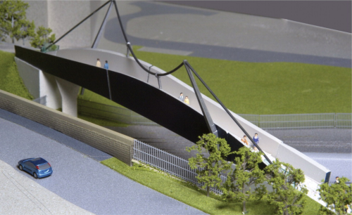
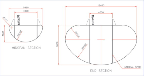
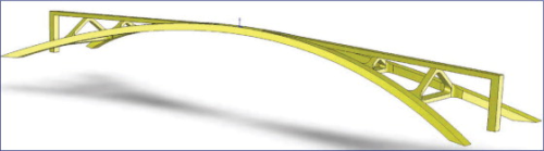
Dr Mark Leaity from White Young Green Consulting described the design and engineering of the bridge structure. The Haughton Road footbridge is the largest all-FRP footbridge to be designed for the rail network in the UK. It is a 50 m long self-supporting structure with a main span of 40.4 m and a secondary span of 8.1 m at the NE end. The bridge is highly skewed and supported on concrete abutments and a single concrete pier. A skewed stainless steel cable slung from splayed stainless steel masts provides a decorative feature over the bridge but does not provide any structural support. A scale model of the bridge is shown in Figure 8.
The bridge structure is to be produced using resin infusion or prepreg moulding with vinyl ester or epoxy resins to achieve a high fibre content and good quality laminates to last the 120 year design life. Some smaller and repetitive internal components such as internal frames may be produced using resin transfer moulding. The majority of the structure consists of glass fibre reinforced sandwich panels with structural foam cores. A small amount of unidirectional carbon fibre is used to improve the stiffness of the structure and achieve the necessary dynamic performance.
A cross-section through the bridge is an unbalanced U shape with profiled parapets splayed out at 10°; to the vertical and varying in height from 1.5 m to 3.1 m above deck level to give an interesting sculptural form. The tops of the parapets are reinforced with unidirectional carbon fibres and below the 3 m wide deck is a 1.1 m deep torque box. The complete assembly is bonded together with structural adhesives and the whole bridge will weigh around 20 tonnes.
The bridge has been analysed for load effects as laid down by BD37/01 Loads for Highway Bridges including dead loads, live loads of 5 kN/m2, wind loads, thermal expansion and differential settlement as well as dynamic loading and response due to pedestrian excitation and train aerodynamic buffeting. Dynamic analysis under pedestrian excitation has identified that tuned mass dampers will be required to damp the dynamic response to comfortable levels for users. This is a common issue with very lightweight bridges and space for dampers has been designed into the structure below the deck at mid-span.
As well as the requirements of design codes, the client (Darlington Borough Council) and Network Rail who have to approve the design, have stipulated that the structure must be resistant to vandalism and fire. Testing has been carried out on candidate materials to demonstrate robustness and self-extinguishing behaviour in a fire. A special aggregate filled coating is to be used to enhance the surface robustness of the parapets and recycled rubber tiles are to be used on the deck.
A critical aspect of the design that has been identified as needing further research is the aerodynamic loads applied to the bridge due to passing trains. This is a critical design case for very lightweight bridges and could result in uncomfortable accelerations of the structure if not adequately evaluated.
Manufacture of the bridge is scheduled to start in late 2007 for installation in early 2008.
The future
David Kendall, from Optima Projects Ltd, presented a look into future with a concept design study to produce a 300 m clear-span FRP footbridge, able to clear the River Thames in London without the need for piers in the river. His opening remarks were to stress that although this was a look into the future, the technology and capabilities existed within the composites industry to build such a large structure today. To prove this he presented examples of existing large FRP structures ranging from mass produced 60 m long wind turbine blades to very large one-off structures such as the 75 m long sailing yacht Mirabella V.
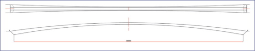
Kendall then presented details, including construction costs, of some recent long footbridges including the two Hungerford Bridges and the Millennium Bridge in London and the Simone de Beauvoir Bridge in Paris. All were around 300 m overall length with the two London bridges having piers in the river. These bridges used steel, concrete and aluminium in their construction but not any FRP. In all cases a considerable amount of the construction cost was attributed to the on-site works and installation. It was proposed that by using a lightweight carbon-fibre composite primary structure, it would be possible to span the river without the need for very costly supports within the river and thereby dramatically cut installation times and cost. Kendall presented a very simple, ultra-lightweight monocoque structure, spanning 300 m without cable supports, producing an efficient and very durable design, as shown in Figure 9 and Figure 10.
To back up the idea, he presented the results of a finite element analysis study and a cost prediction that showed that the fully installed bridge could cost several million pounds (£) less than the Millennium or Hungerford bridges, simply based on initial capital costs, without needing to take into account the significant advantages of reduced maintenance through the life of the structure.
Kendall also presented some further developments of this large carbon structure, introducing more three-dimensional forms to improve the stiffness of the structure without adding any extra material, as shown in Figure 11. This work certainly demonstrates great potential and shows how advanced composites used intelligently can provide cost-effective and often dramatic solutions.
New projects
The NGCC conference was deemed to be a great success and demonstrated the numerous advantages in using composites for footbridge structures. Importantly the major asset owners are now beginning to realise the potential advantages and in some cases are specifying that FRP is to be used for certain new projects. Once these initial structures are installed this should help to accelerate the development of new structures and this is expected to become an established market area for the composites industry. We have seen how the composites industry has the expertise and capabilities to deliver major structural projects and it is hoped that this can be used effectively to build some large and efficient footbridge structures.


