
![Figure 7: Thermoplastic unidirectional tapes (top); braided tape preform (middle); consolidated braid based on tapes (bottom) [7].](/media/1jenjpvq/f5781b77-daa7-46cd-8739-61b74022cd05.jpg)
Part 2 of Expanded role for thermoplastic composites - read Part 1
Textile technologies meet thermoplastic composites
Quasi-isotropic laminate design is currently often used for composites. This derives from established design methodologies that are very conservative. In order to exploit more of the theoretical lightweight potential, a load path-oriented fibre architecture has to be achieved. The required design and simulation methods are already available today in R&D and industrial pre-development scale. In the manufacturing arena, textile-based technologies involving fabrics, fibre placement via embroidery technology or braiding are suitable for generating fibre architectures oriented to load conditions and modern design methodologies. These manufacturing techniques are based on classic textile technologies and are used today within the composites industry to produce a so-called textile preform. The preform is built up with dry fibre materials like carbon fibre yarns and is subsequently impregnated with the polymer. This section shows the potential of UD tape-based fabrics and the feasibility of manufacturing complex hollow CFRTP structures by overbraiding technologies.
Fabric production and processing
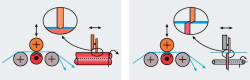
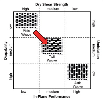
Fabrics based on fully impregnated and consolidated UD tapes have been produced in a development scale by SGL Group. Master tapes with a width of more than 200 mm were cut into so-called slit tapes of 18 mm width. The weaving technology needs a material of constant width with sharp, precise edges. Together with the mechanical requirement of composites for tapes with high parallelism, this necessitates an advanced slitting technology. To identify a slitting technology that fulfills these requirements, two different slitting technologies were tested and evaluated – scissor-type and squeeze-type cut. The principle of both types are shown in Figure 3. It can be seen in the diagram on the left that a fixed and a flexible knife are used to cut or squeeze the material in the squeeze-type method. This leads to poor cutting quality with undulated and damaged tape edges. In contrast to this, the scissor-type cut (right) uses two rotating knifes positioned obversely. Here the material is much better preserved during cutting, giving rise to a high-quality cutting result. Using the scissor-type cut in a machine with web edge control, slit tapes suitable for the weaving process can be produced. The slit tapes are processed on an industrial loom machine to produce a fabric with plain-weave fibre architecture. As shown in Figure 4, the single layer of UD tape-based fabric still exhibits textile behaviour. This plain-weave fabric can be fixed by a pressing process to a single-layer organic sheet with two reinforcing fibre directions. Stacked single-layer fabrics or sheets can be translated into an organic sheet that can be processed in a subsequent thermoforming process into the final structural component. Depending on the fibre architecture of the fabric, processing behaviour and the resulting mechanical properties are different. Figure 5 shows the shear strength, drapability, fibre undulation, and mechanical in-plane performance obtained with three different fibre architectures of classic textile fabrics. The red arrow in Figure 5 shows that the in-plane shear strength is lower for the UD tape fabrics. This is related to the smooth surfaces of the tapes, which can result in sliding of the individual tape or complete fibre architecture.
Owing to the thin UD tapes, undulation within the textile architecture is also lower for the thermoplastic UD tape-based fabrics than for a conventional textile fabric. In-plane mechanical performance is therefore increased. Nevertheless, fabric architecture typically results in lower in-plane mechanical properties than a unidirectional layer. But SGL was able to show that the low undulation level of the thermoplastic UD tape-based fabrics leads to a performance loss of less than 10% compared with a unidirectional laminate. This can be accepted if other process and mechanical parameters can be positively influenced. The textile behaviour of the thermoplastic UD tape-based fabric enables controlled draping during the thermoforming process. This controlled and regulated draping leads to optimised fibre architecture in the final geometry, so promoting optimised lightweight design with respect to load path-oriented laminates.
Overbraiding technology
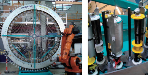
Modern braiding technology for composite applications goes back to traditional textile techniques. Even state-of-the-art machines combined with six-axis industrial robots, shown in Figure 6, use technical principles that can be seen in traditional machines. The spools are moved by horn gears in sinusoidal tracks; one fibre system in the clockwise direction, the other one in the opposite. The contra-rotating bobbins and fibres intertwine and form a closed textile at the braiding point [6]. In the near net shape preforming process, a mandrel of arbitrary shape is manipulated through the braiding ring so the braided textile is deposited directly on the mandrel. For thick and layered preforms this process can be repeated several times. Braiding technology for composites in the automotive and aerospace industries currently uses dry yarn systems. So Liquid Resin Infusion (LRI) methods must be employed in a second, separate manufacturing step to infiltrate and consolidate the textile preform with the polymer. This adds process steps within the manufacturing process chain and therefore leads to higher production costs. SGL Group is currently involved in different research and development activities aimed at using superior pre-impregnated yarns like thermoplastic unidirectional tapes (see Figure 7 top) in the braiding processes. It has been demonstrated that it is feasible to produce tubular structures with thermoplastic UD tapes by the braiding process (see Figure 7 middle). The resulting textile preform, based on fully consolidated thermoplastic UD tapes, has to be pressed into the final laminate, as shown in Figure 7 (bottom) in a subsequent process step. Compared with the LRI methods already described, the preform impregnation and consolidation steps can be eliminated. This time saving can result in an overall cost advantage for the structural component.
Conclusion and outlook
For a thermoplastic material system, customised sizing technologies are the key to high-performance fibre-matrix interaction with subsequent top mechanical performances in the laminate level. The process technology for the production of UD tapes is determined by the different grades of raw material used. This ultimately has a significant impact on the cost structure of the semi-finished product. In addition, the textile preforming capability of superior pre-impregnated materials like thermoplastic unidirectional tapes is shown in overbraiding and fabric-based processes. Preforming technologies using pre-impregnated materials can be the key to overcome existing cost challenges.
Acknowledgments
University of Stuttgart; Institute for Aircraft Design (IFB): Figure 6; braiding machine. Some results relating to process technologies for UD tapes were obtained in a research project carried out within the publicly funded ‘MAI Carbon’ Leading Edge Cluster.
References
1. G. W. Ehrenstein; ‘Faserverbund-Kunststoffe: Werkstoffe, Verarbeitung, Eigenschaften’, 2nd edition, Hanser, München, 2006. 2. H. Schürmann; ‘Konstruieren mit Faser-Kunststoff-Verbunden’, Springer Verlag, 2007. 3. M. Flemming, S. Roth, G. Ziegmann; ‘Faserverbundbauweisen: Fasern und Matrices’, Springer, Berlin, 1995. 4. A. Erber, S. Spitko; ‘Customized Sizing Solutions for Carbon Fibre reinforced Polymers’; I.C.S. Conference; March 2014; Paris. 5. Manuscript ‘Composite Processing” of TU Munich; Chair for Carbon Composites (LCC). 6. A. Erber, K. Drechsler; ‘Damage Tolerant Drive Shafts with Integrated CFRP Flanges’; SAMPE Seattle Conference 2010. 7. A. Erber; ‘Material Innovations and Design Concepts for Thermoplastic Composites’; 4th International Congress Automotive Composites; December 2013; Cologne.
Part 2 of Expanded role for thermoplastic composites - read Part 1
This article was published in the July/August 2014 issue of Reinforced Plastics magazine.
The digital edition of Reinforced Plastics is distributed free of charge to readers who meet our qualifying criteria. You can apply to receive your free copy by completing this short registration form.


